
Dipole with an unbalanced microstrip feed

a microstrip and dipole technology, applied in the direction of antennas, antenna feed intermediates, electrically short antennas, etc., can solve the problems of increasing either the depth or the area of the assembly, and achieve the effect of reducing the size, complexity and feed loss of the feed circui

Inactive Publication Date: 2014-11-04
THE UNITED STATES OF AMERICA AS REPRESENTED BY THE SECRETARY OF THE NAVY
View PDF3 Cites 14 Cited by
  • Summary
  • Abstract
  • Description
  • Claims
  • Application Information

AI Technical Summary

Benefits of technology

The invention provides a linearly polarized dipole antenna with an unbalanced microstrip feed line that eliminates the need for a balun circuit, reducing the size and complexity of the feed circuit. This results in a more compact and efficient antenna design. It is suitable for dipoles with small ground planes and does not require a separate circuit board. The antenna has a substrate with a microstrip feed line and ground plane, along with two conductive elements that extend through the ground plane aperture and make contact with the microstrip feed line and substrate. This design simplifies the connection between the feed and ground, reduces feed loss, and improves antenna performance.

Problems solved by technology

Depending on how the balun circuit was implemented, it had the undesired effect of increasing either the depth or area of the assembly.

Method used


Image

  • Dipole with an unbalanced microstrip feed
  • Dipole with an unbalanced microstrip feed
  • Dipole with an unbalanced microstrip feed

Examples


Embodiment Construction

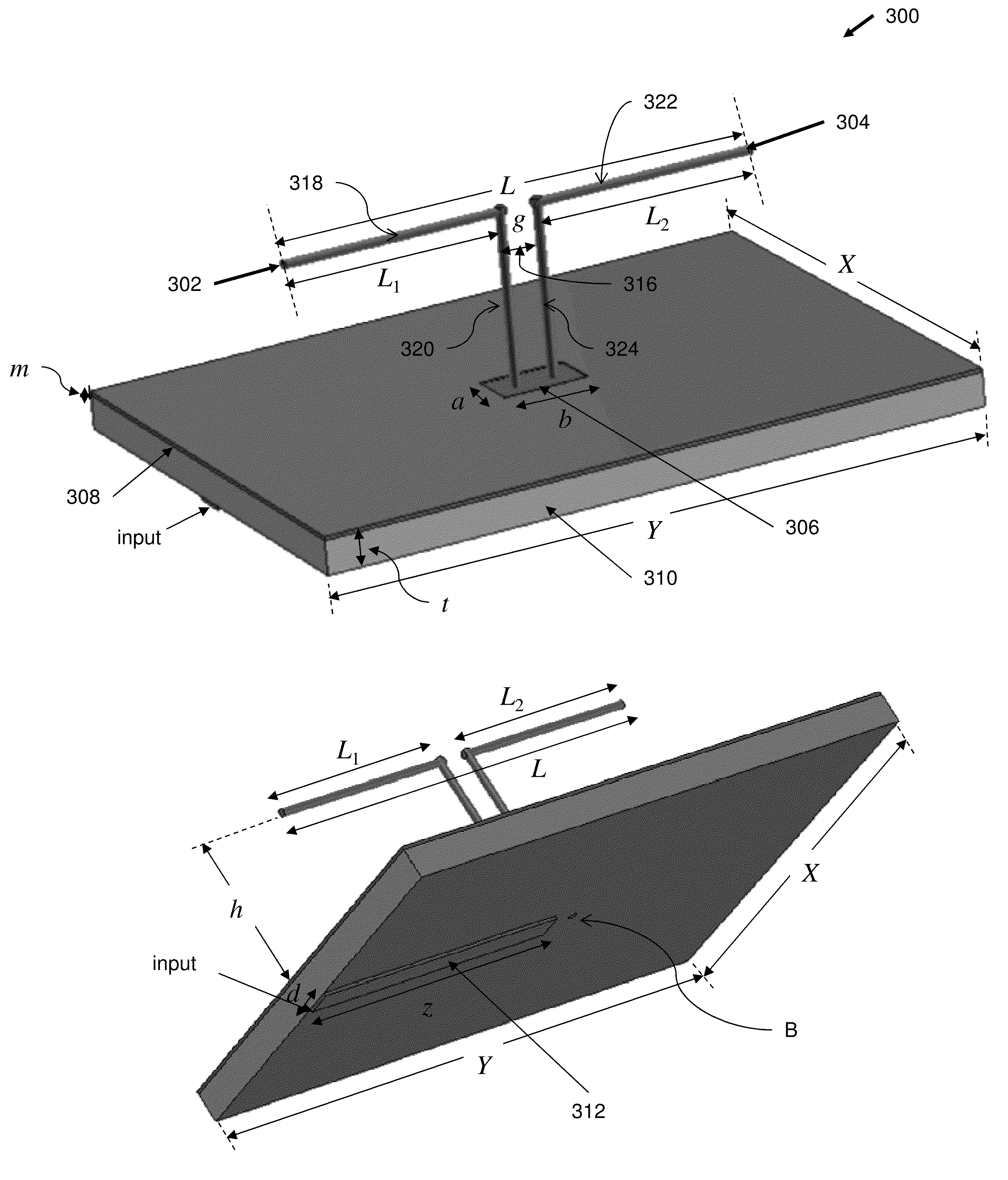
[0023]FIGS. 3A and 3B and 3C illustrate a linearly polarized dipole antenna assembly with unbalanced microstrip feed line in accordance with one embodiment. FIG. 3A illustrates a transverse top view of a linearly polarized dipole assembly 300 with unbalanced microstrip feed line in accordance with one embodiment. FIG. 3B illustrates a transverse bottom view of the linearly polarized dipole assembly of FIG. 3A in accordance with one embodiment. FIG. 3C illustrates a side view of the linearly polarized dipole assembly of FIG. 3A in accordance with one embodiment.

[0024]Referring to FIGS. 3A, 3B, and 3C, in one embodiment, linearly polarized dipole antenna assembly 300 includes two elements: a conductive first dipole element 302, and a conductive second dipole element 304. In one embodiment, a first end of first dipole element 302 extends through a ground plane aperture 306 in a top surface of a ground plane 308 through a substrate 310 and is attached to a microstrip feed line 312 at a ...


PUM


Abstract

Embodiments in accordance with the invention include a linearly polarized dipole antenna with an unbalanced microstrip feed line. More specifically, embodiments in accordance with the invention utilize a fed dipole connected to a microstrip feed line, and separated a gap distance from a parasitic dipole not connected to the microstrip feed line. When an electrical signal is input to the microstrip feed line, the microstrip feed line creates a current flow in the fed dipole which induces a nearly equal current on the parasitic dipole that is out of phase. The result is a current flow, I, in the same direction in both fed and parasitic dipoles allowing for efficient radiation of the linearly polarized dipole antenna. Embodiments in accordance with the invention eliminate the need for a balun circuit thereby reducing the size, complexity and feed loss of the feed circuit. Embodiments in accordance with the invention are effective for dipoles with relatively small ground planes.

Description

CROSS-REFERENCE TO RELATED APPLICATIONS[0001]This application claims the benefit of U.S. Provisional Application No. 61 / 599,308 filed Feb. 15, 2012, which is hereby incorporated in its entirety by reference.BACKGROUND OF THE INVENTION[0002]1. Field of the Invention[0003]The present invention relates generally to dipole antennas.[0004]2. Description of the Related Art[0005]Linearly polarized dipole antennas are commonly used in communication and radar applications. Dipoles can be used individually or as elements in an array antenna. Often a dipole antenna is fed using a microstrip feed line. Microstrip feed lines are utilized in many applications because the devices connected to the dipole are often printed on microstrip boards.[0006]Prior art dipole structures utilized a balanced structure that generally required a balanced-to-unbalanced circuit, also termed a balun circuit, or simply a balun, when fed by a microstrip line. Depending on how the balun circuit was implemented, it had ...

Claims


Application Information

Patent Timeline
Patent Type & Authority Patents(United States)
IPC IPC(8): H01Q9/16
CPCH01Q9/16
Inventor JENN, DAVID, C.
Owner THE UNITED STATES OF AMERICA AS REPRESENTED BY THE SECRETARY OF THE NAVY
Learn More