
Protective apparatus for windows and construction areas

a technology for protecting equipment and construction areas, applied in the direction of applications, machine supports, building scaffolds, etc., can solve the problems of damage, loss of time and money devoted to cleanup and repair, and damage, so as to prevent the spread of contaminants and increase efficiency.

Inactive Publication Date: 2014-11-04
FLORES GARRETT
View PDF51 Cites 18 Cited by
  • Summary
  • Abstract
  • Description
  • Claims
  • Application Information

AI Technical Summary

Benefits of technology

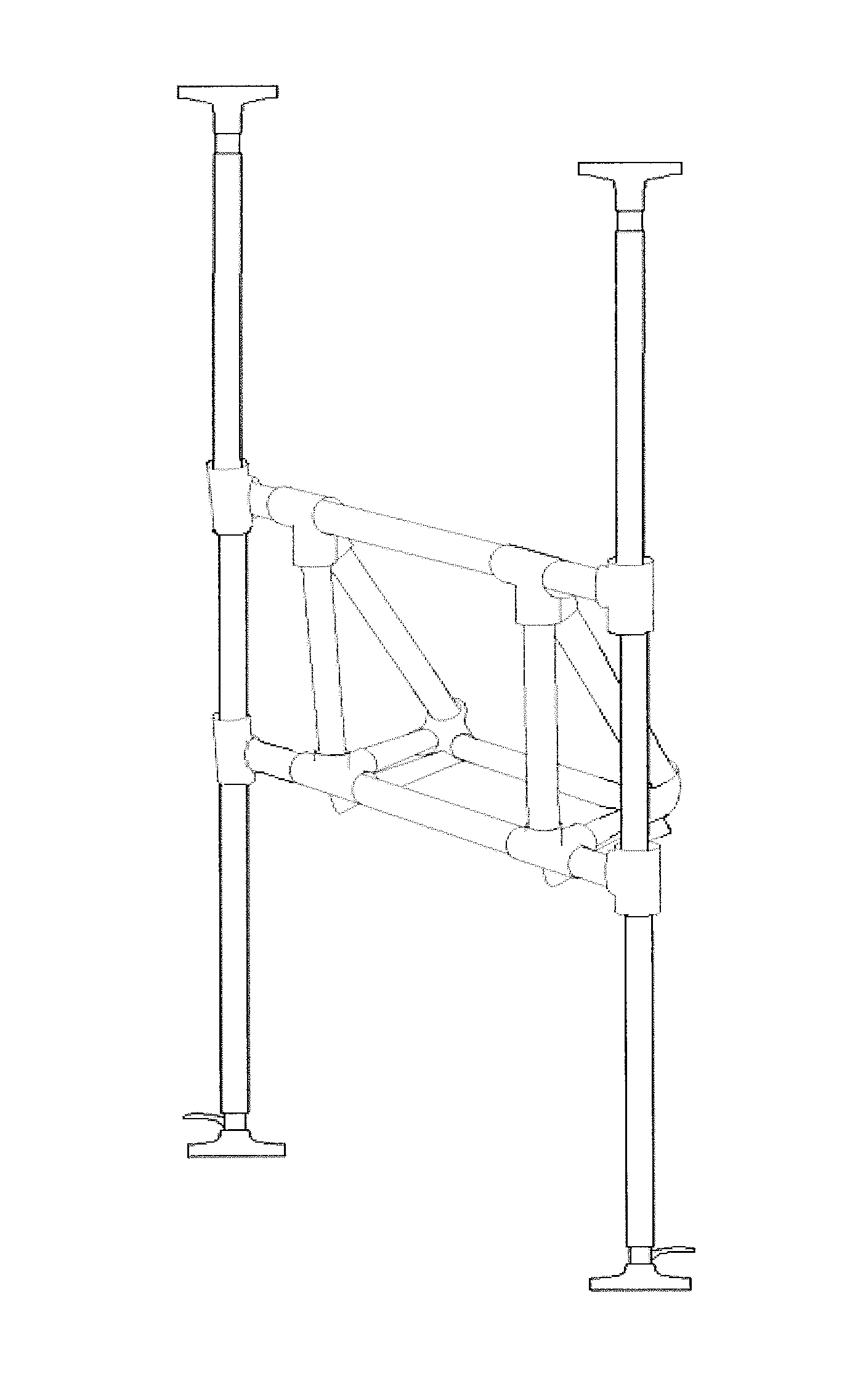
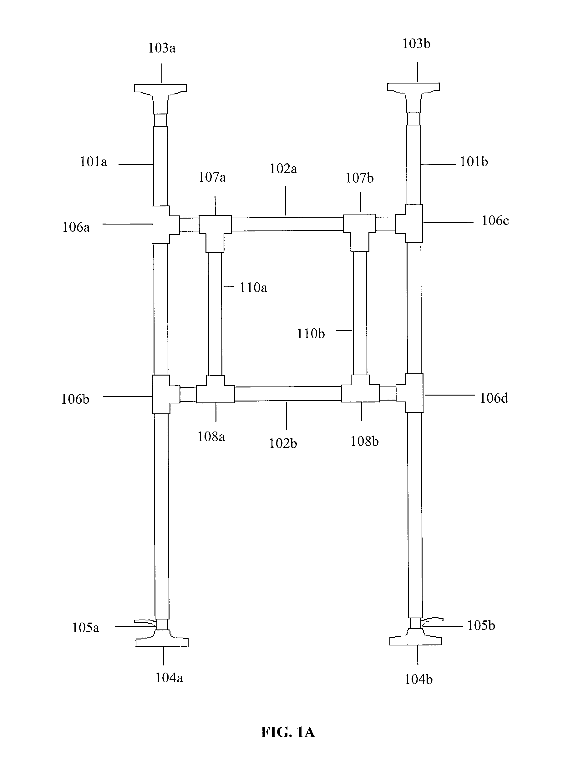
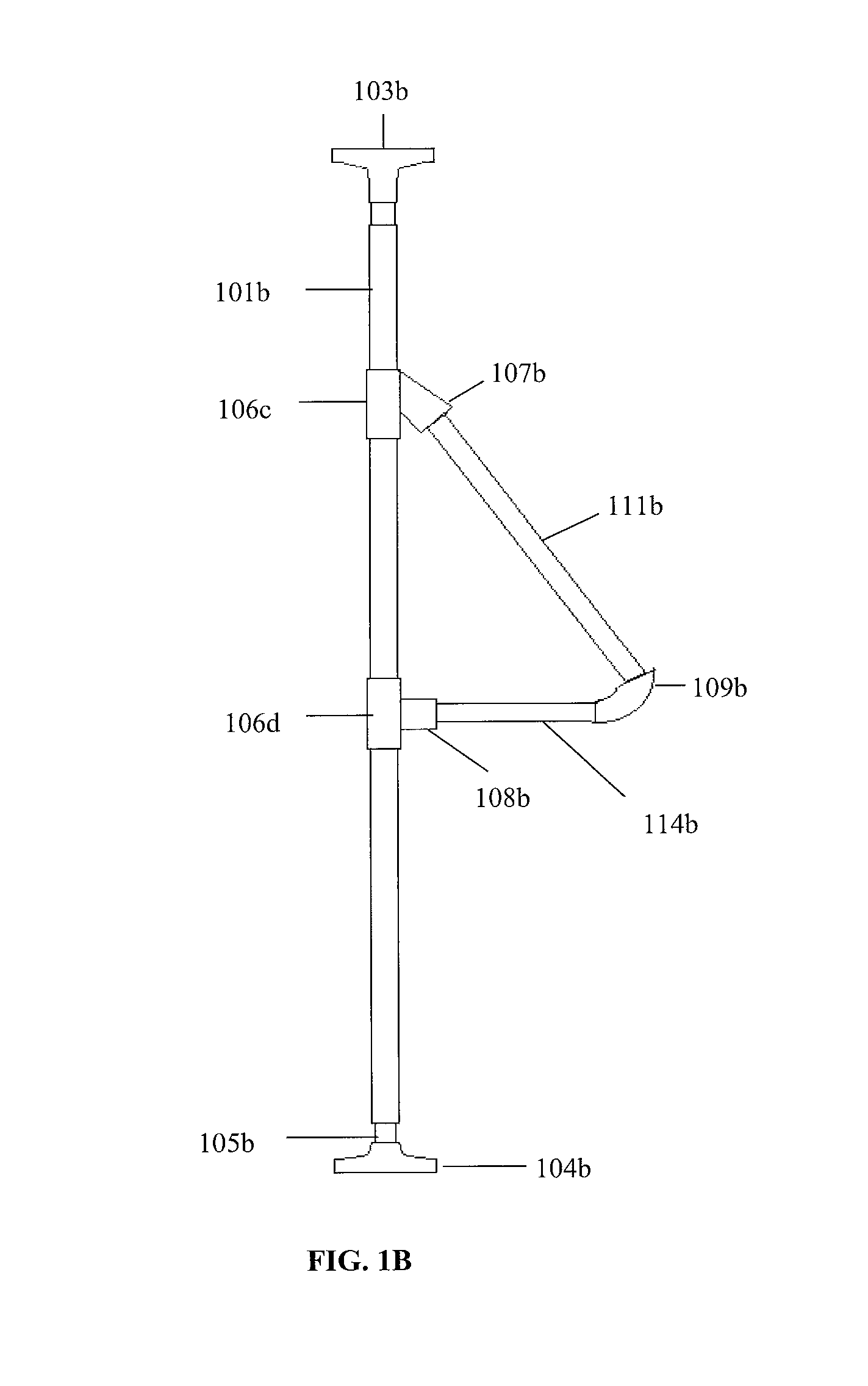
The present invention is a device that allows materials to pass through a window without exposing them to the surrounding environment. The device includes a center frame with a rotating segment, which keeps the materials atop it as they are transported. This prevents damage to the materials and minimizes the potential for debris to spread throughout the room. The device can be used in construction, healthcare, and delivery applications to provide efficient and safe transportation of items.

Problems solved by technology

Materials that hit the window frame or doorway can cause damage, requiring repair or replacement.
Even if workers use great care to avoid any damage, passing materials through windows or doors is likely to cause some damage eventually.
Such damage results in lost time and money devoted to cleanup and repair.
However, cloth and plastic material do not protect from moderate or severe impacts, and provide little protection against significant damage such as breaks or indentations in the window sill, door frame, molding, flooring or other exposed surface.
Construction projects also produce debris such as dust and small pieces of work materials.
Further, debris may fall or scatter while transporting materials inside a building.
This requires in additional time and effort, increasing the overall cost of the construction project.
While this method prevents materials from coming into direct contact with the floor, a tarp does not prevent the dispersion of debris throughout the surrounding areas.
For example, sawdust may blow into adjacent rooms, or paint may splatter onto ceilings or walls.

Method used


Image

  • Protective apparatus for windows and construction areas
  • Protective apparatus for windows and construction areas
  • Protective apparatus for windows and construction areas

Examples


Embodiment Construction

[0029]A detailed illustrative embodiment of the present invention is disclosed herein. However, techniques, systems and operating structures in accordance with the present invention may be embodied in a wide variety of forms and modes, some of which may be quite different from those in the disclosed embodiment. Consequently, the specific structural and functional details disclosed herein are merely representative, yet in that regard, they are deemed to afford the best embodiment for purposes of disclosure and to provide a basis for the claims herein which define the scope of the present invention.

[0030]None of the terms used herein, including “floor”, “ceiling”, “wall”, “vertical”, “horizontal” and “diagonal” are meant to limit the application of the invention. The terms are used to illustrate the preferred embodiment and are not intended to limit the scope of the invention. Similarly, the use of these terms is not meant to limit the application of the invention, as the invention is...


PUM


Abstract

The invention relates to the general field of construction, and more specifically, the protection of construction work sites. At least two vertical poles are positioned between two surfaces such as ceilings and floors. A center frame with one or more rotatable segments may be mounted between the vertical poles and secured to a window sill. Construction materials may be passed over the rotatable segment and through the center frame with minimal or no damage to the window sill or surrounding structure. The vertical poles may be used with a sheet material to form a protective tunnel. Construction materials may be passed through the tunnel with minimal or no damage to the surrounding environment. Debris left by the construction materials is captured within the tunnel and can be safely and conveniently removed.

Description

BACKGROUND OF THE INVENTION[0001]Construction projects typically include the demolition, transportation and reconstruction of materials. In a typical home construction or renovation, materials may be passed into or out of the house through a window frame or doorway. Materials that hit the window frame or doorway can cause damage, requiring repair or replacement. Even if workers use great care to avoid any damage, passing materials through windows or doors is likely to cause some damage eventually. Such damage results in lost time and money devoted to cleanup and repair.[0002]To minimize the potential for damage, workers may place cloth or plastic material over window sills or flooring to protect them from minor damage. However, cloth and plastic material do not protect from moderate or severe impacts, and provide little protection against significant damage such as breaks or indentations in the window sill, door frame, molding, flooring or other exposed surface. Thus, there exists a...

Claims


Application Information

Patent Timeline
Patent Type & Authority Patents(United States)
IPC IPC(8): A47F5/00E04F21/00E04G21/14E06B7/28E04D15/00A47G5/00
CPCE04G21/247E04G7/14E04G21/243E04G21/30E04G2025/006
Inventor FLORES, GARRETT
Owner FLORES GARRETT
Learn More