
Modular building system

a modular building and building technology, applied in the field of modular building systems, can solve the problems of reducing the level of skilled labor required to complete the assembly of building components at the construction site, rigid connections, etc., and achieve the effects of high robustness and stability, fast erection, and low manufacturing cos

Active Publication Date: 2014-11-04
PALMERI RICHARD
View PDF35 Cites 4 Cited by
  • Summary
  • Abstract
  • Description
  • Claims
  • Application Information

AI Technical Summary

Benefits of technology

[0006]The disclosed embodiments provide a modular building system using economical components that may be assembled on a construction site using relatively unskilled labor, yet which results in a highly robust and stable building that may withstand flexing and movement due to earthquakes or hurricane force winds. The disclosed modular building system employs an exterior floating curtain wall formed of pre-fabricated modular wall panels that are inexpensive to fabricate and which may be quickly erected in the field. The curtain wall is substantially free floating, and may therefore move and / or flex independent of the building's load bearing components, thereby substantially reducing or eliminating potential telegraphed or reactive movement during earthquakes and hurricanes which may result in greater damage to the building and / or injury to its occupants. The modular components may be fabricated using inexpensive, locally available materials, making the modular building system well suited for use in building low cost structures in remote construction sites where transportation of traditional building materials to the site may be prohibitively expensive or impractical, and skilled labor may not be available.

Problems solved by technology

Using this modular construction approach, a large portion of the labor, including plumbing, wiring and mechanical work, is performed in the factory using production line techniques, thereby reducing the level of skilled labor required to complete assembly of the building components at the construction site.
However, these rigid connections may represent a disadvantage during seismic events and high winds which may impose extraordinary loads on the building.

Method used


Image

  • Modular building system
  • Modular building system
  • Modular building system

Examples


Embodiment Construction

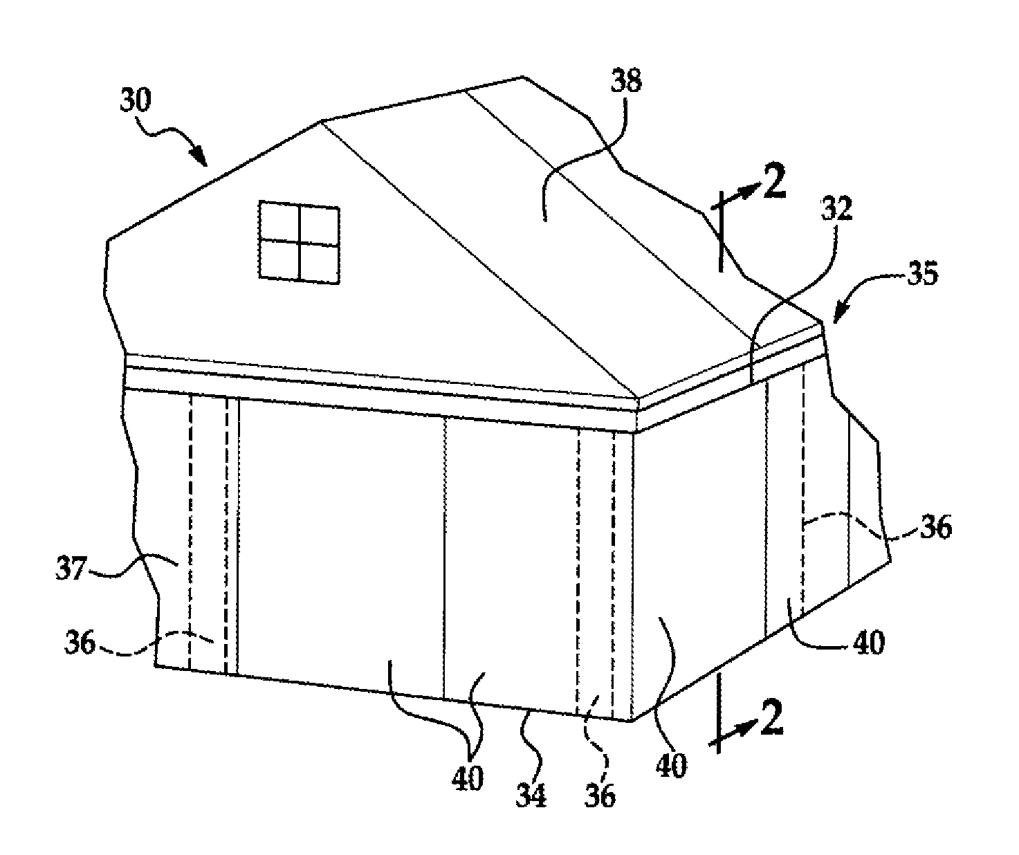
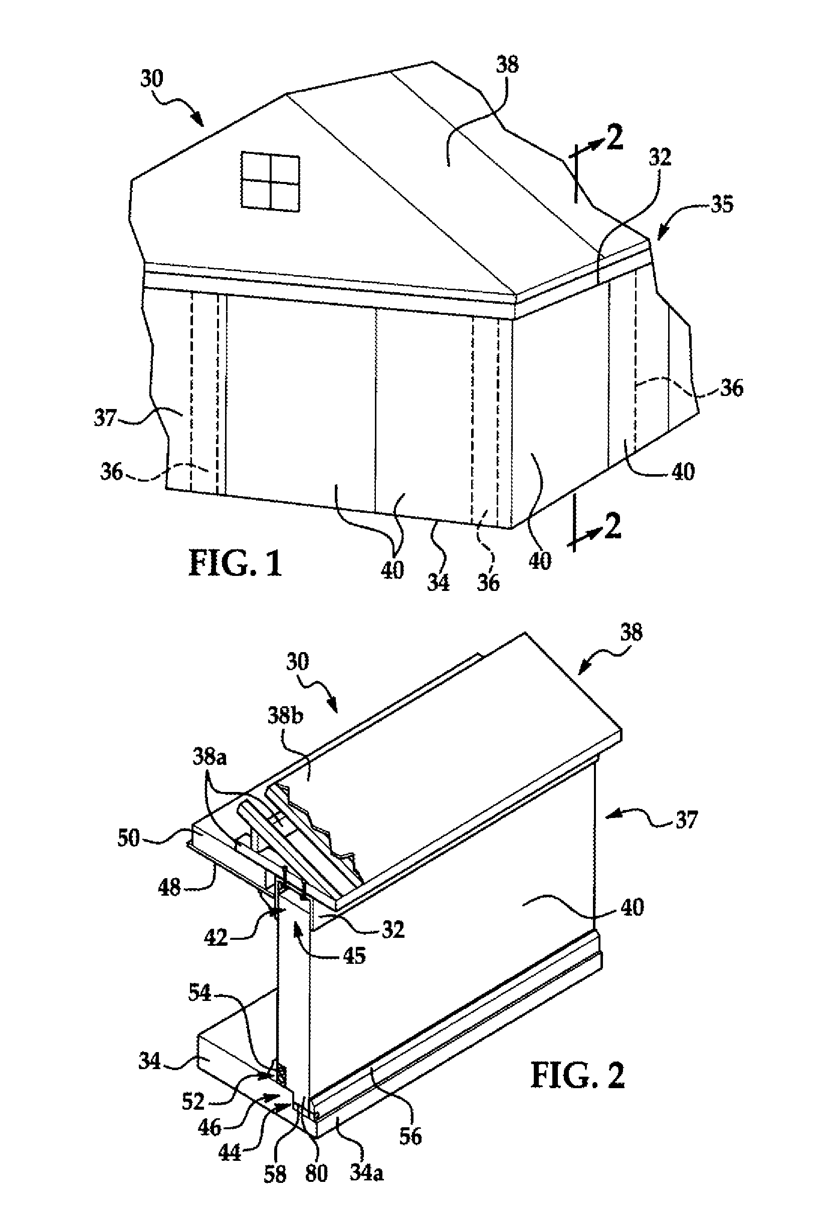
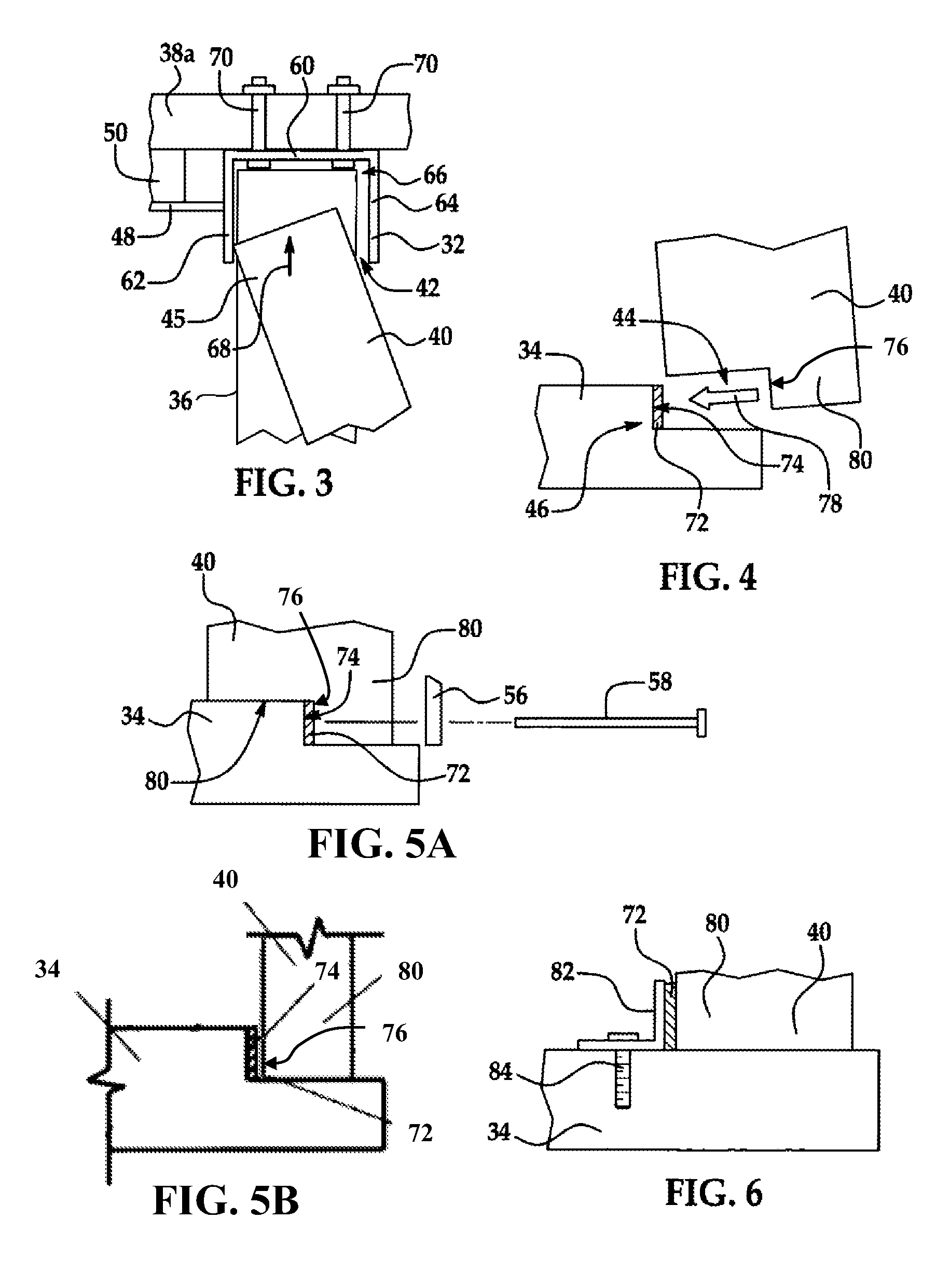
[0037]Referring first to FIG. 1, the disclosed embodiments relate to a modular building system for constructing a building 30. While a single story building 30 is shown in FIG. 1, the disclosed modular building system may be employed in constructing multi-storied buildings as well. The building 30 comprises a load bearing skeletal structure or frame 35, and a non-load bearing, outer curtain wall 37 formed by a plurality of modular wall panels 40 arranged end-to-end with each other. The frame 35 comprises a bond beam 32 which extends substantially continuously around the entire parameter of the building 30, secured to and supported by a plurality of spaced apart vertical posts 36 which support both the dead and live weight on the building 30. The posts 36 are secured to and are supported on around a foundation 34, which may comprise a concrete slab. As will be discussed in more detail below, the bond beam 32 as well as the posts 36 may comprise any of a variety of rigid materials, an...


PUM


Abstract

A modular building system uses a perimeter bond beam and prefabricated wall panels to form an exterior curtain wall. The wall panels are captured within, and may move vertically inside a channel formed in the bond beam. The wall panels are quickly erected by inserting an upper edge of each panel into the channel and swinging the panel onto the foundation where it is claimed in place on the foundation.

Description

TECHNICAL FIELD[0001]This disclosure generally relates to building construction, and deals more particularly with a building system using modular components, particularly those that can tolerate earthquakes and / or high winds. The disclosure also relates to a method of constructing a building using the modular components.BACKGROUND OF THE INVENTION[0002]Buildings constructed from modular components are well known in the art. In one approach, modular components are assembled into sub-assemblies in a factory environment using standardized assembly techniques. The components may include room modules, wall sections, trusses and the like that are shipped to the construction site and assembled. Using this modular construction approach, a large portion of the labor, including plumbing, wiring and mechanical work, is performed in the factory using production line techniques, thereby reducing the level of skilled labor required to complete assembly of the building components at the constructi...

Claims


Application Information

Patent Timeline
Patent Type & Authority Patents(United States)
IPC IPC(8): E04B7/00E04B5/00E04B1/24E04B7/04E04B2/74E04B1/00
CPCE04B2001/249E04B2001/2481E04B7/04E04B2001/2466E04B1/24E04B2/7407E04B2001/2463
Inventor PALMERI, RICHARD
Owner PALMERI RICHARD
Learn More