
Bolt free electrical bus connector

a technology of electrical bus connectors and bolts, which is applied in the direction of butt joining bus-bars, connection contact material, electrical apparatus, etc., can solve the problems of negative impact on the physical and/or electrical connection between the busway joint pack, and achieve the effect of less material and smaller busway joint pack

Active Publication Date: 2014-10-21
SCHNEIDER ELECTRIC USA INC
View PDF11 Cites 12 Cited by
  • Summary
  • Abstract
  • Description
  • Claims
  • Application Information

AI Technical Summary

Benefits of technology

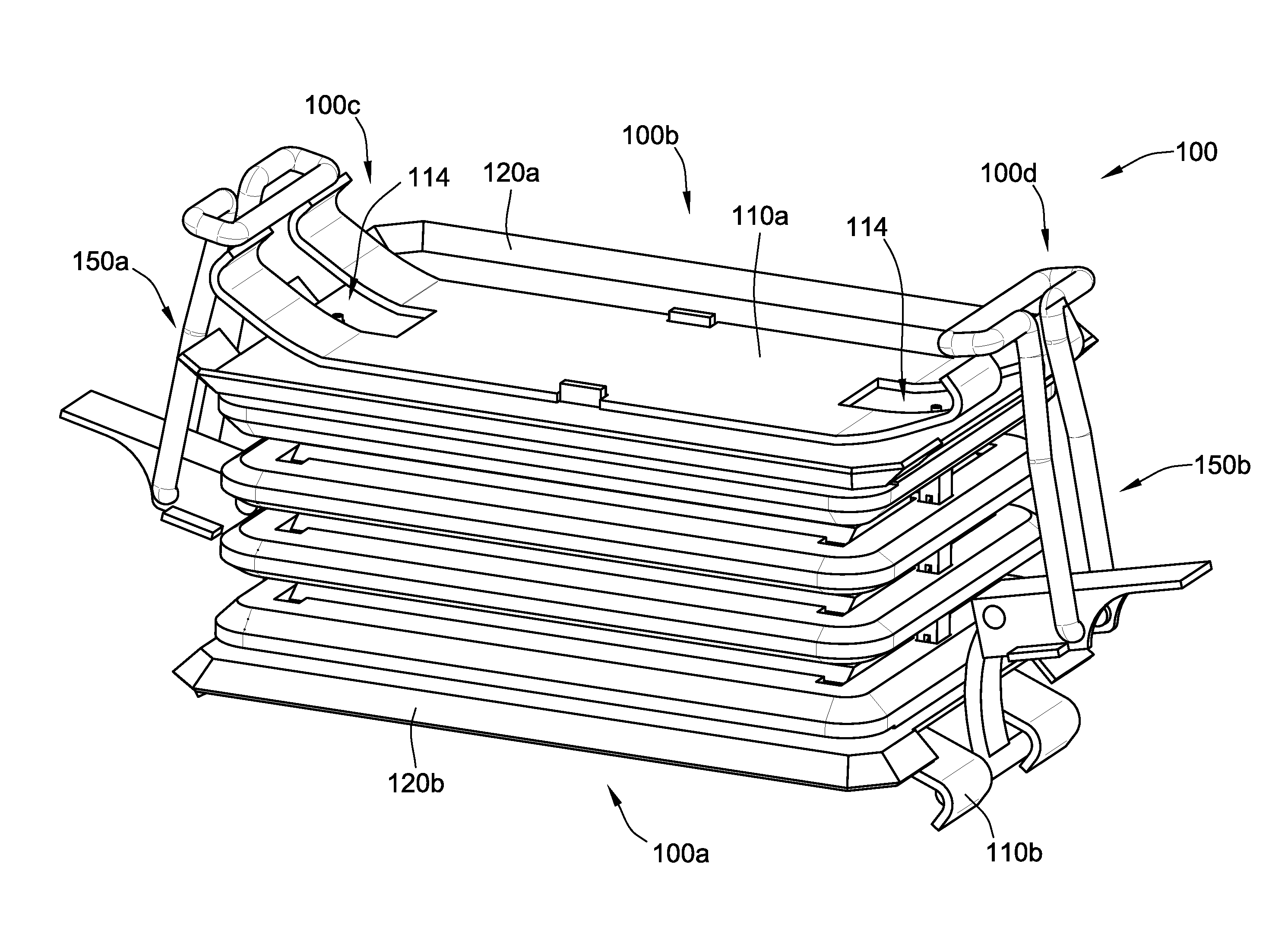
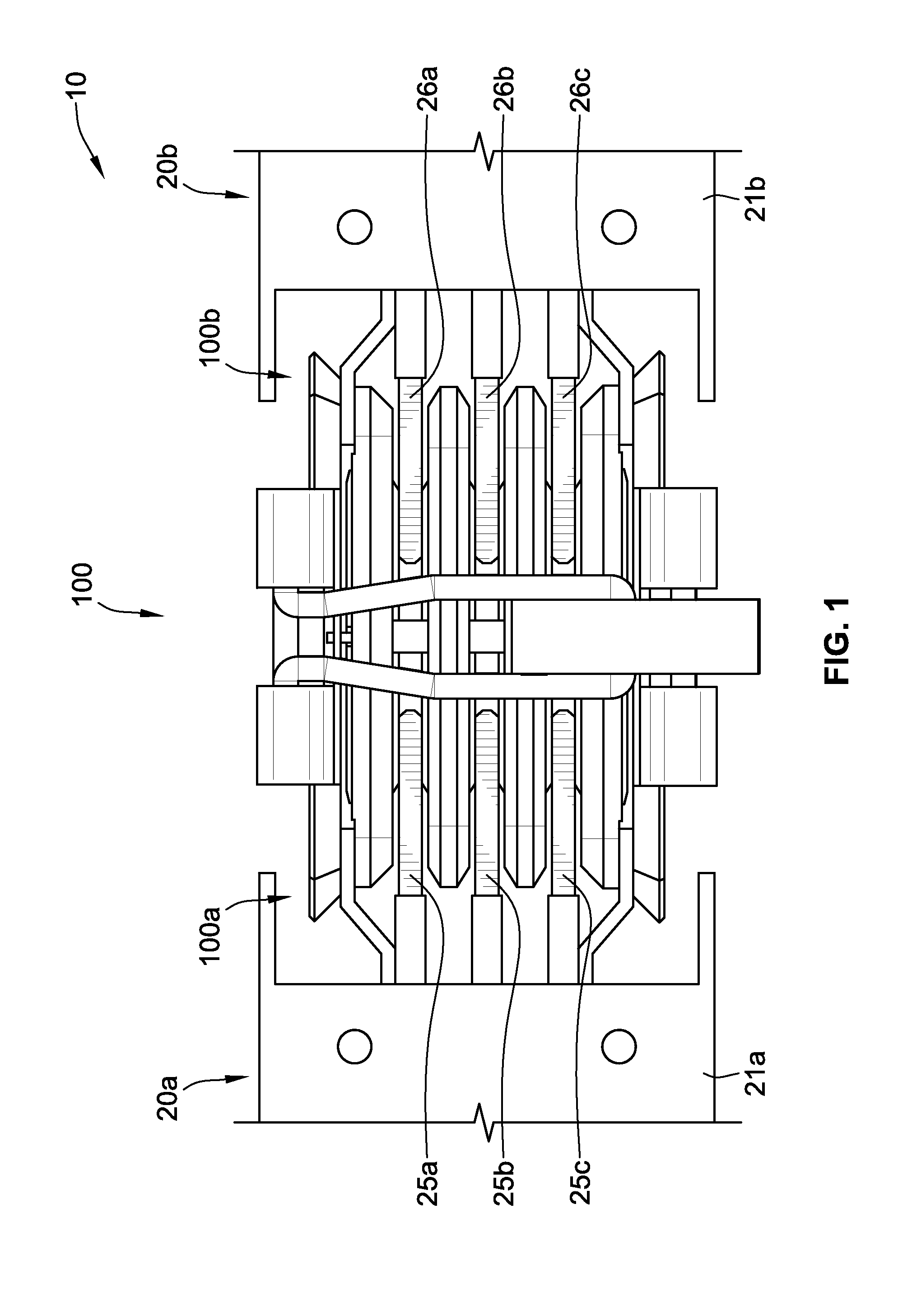
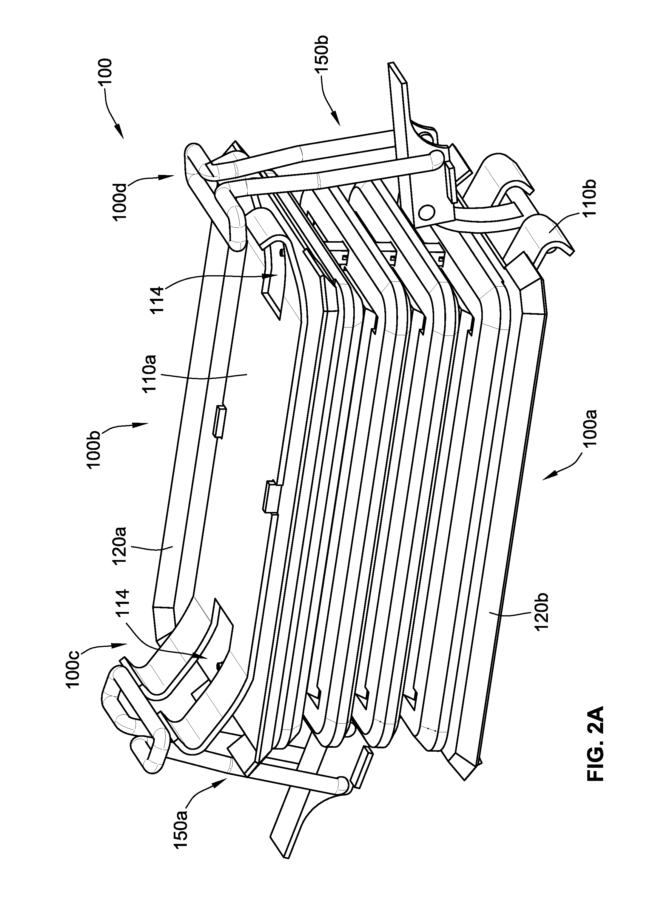
[0006]The present disclosure is directed to providing a bolt-free busway joint pack. Instead of coupling the busway joint pack to a pair of busway sections by tightening a fastener (e.g., bolt) positioned through the center of the busway joint pack, the central fastener is removed and replaced with one or more alternative fasteners (e.g., latch mechanism) positioned at one or both sides of the busway joint pack without having to be positioned through connector plates (e.g., conductive plates made of copper and / or aluminum) of the busway joint pack. By removing the fastener from the center of the busway joint pack, the busway joint pack can be made smaller with less material without compromising the thermal performance of the busway joint pack.
[0007]Further, the busway joint pack of the present disclosure does not require a torque wrench for installation of the busway joint pack in a busway system, as is necessary to install prior joint packs with central bolt fasteners. Instead, the latch mechanisms are simply closed (e.g., thrown) to install the busway joint pack. Such a simple installation method results in the ability to install the busway joint pack without needing a lot of room around the busway joint pack.

Problems solved by technology

Overtime, the busway joint pack endures thermal cycling that can cause the nut to become loosened, thereby negatively impacting the physical and / or electrical connection between the busway joint pack and the busways coupled thereto.

Method used


Image

  • Bolt free electrical bus connector
  • Bolt free electrical bus connector
  • Bolt free electrical bus connector

Examples


Embodiment Construction

[0015]Although the invention will be described in connection with certain aspects and / or embodiments, it will be understood that the invention is not limited to those particular aspects and / or embodiments. On the contrary, the invention is intended to cover all alternatives, modifications, and equivalent arrangements as may be included within the spirit and scope of the invention as defined by the appended claims.

[0016]Words of degree, such as “about”, “substantially”, and the like are used herein in the sense of “at, or nearly at, when given the manufacturing, design, and material tolerances inherent in the stated circumstances” and are used to prevent the unscrupulous infringer from unfairly taking advantage of the invention disclosure where exact or absolute figures and operational or structural relationships are stated as an aid to understanding the invention.

[0017]Referring to FIG. 1, a busway system 10 is shown. The busway system 10 includes a busway joint pack or joint pack 1...


PUM


Abstract

A busway joint pack includes a first latch mechanism having an open position and a closed position and a second latch mechanism having an open position and a closed position. The busway joint pack further includes a first connector plate having a first major surface opposing a second major surface and a second connector plate having a first major surface opposing a second major surface. The second connector plate is spaced from the first connector plate such that the first and the second connector plates are configured to engage phase conductors of busway sections in a clamping fashion when to the first latch mechanism is in the closed position and the second latch mechanism is in the closed position. The busway joint pack lacks a fastener positioned through the center of the first and the second connector plates, but is rather held together by the latch mechanisms.

Description

FIELD OF THE INVENTION[0001]The present invention relates generally to electrical distribution equipment and, more particularly, to bolt free electrical bus connectors.BACKGROUND OF THE INVENTION[0002]A busway system typically includes two or more busway sections, one or more busway joint packs (e.g., electrical bus connectors) for connecting two busway sections together, and may include multiple plug-in units. Each busway section includes one or more phase-conductors and a housing. For example, in a three-phase system, the busway section can include three live phase-conductors or three live phase-conductors and one neutral-conductor, depending on the type of system architecture being employed. If required, various plug-in units or electrical components can be directly connected to one or more plug-in connection sites spaced along the busway sections to draw power. Each busway joint pack is used to physically and electrically connect two busway sections or two sets of busway togethe...

Claims


Application Information

Patent Timeline
Patent Type & Authority Patents(United States)
IPC IPC(8): H01R4/60
CPCH02G5/007
Inventor WALGENBACH, JACOB E.DOZIER, STEVEN WAYNE
Owner SCHNEIDER ELECTRIC USA INC
Learn More