
Preoperative planning program and operation support jig for hip replacement arthroplasty

a hip replacement and preoperative planning technology, applied in the direction of prosthesis, instruments, osteosynthesis devices, etc., can solve the problems of not being applied to the femoral side having a different bone shape or function axis or any other, and being subjected to degenerative destruction

Inactive Publication Date: 2014-10-14
LEXI CO LTD
View PDF16 Cites 15 Cited by
  • Summary
  • Abstract
  • Description
  • Claims
  • Application Information

AI Technical Summary

Benefits of technology

The present invention provides a preoperative planning program and an operation support jig for hip replacement arthroplasty. The program allows a computer to input tomographic images of a patient's lower extremities and reconstruct a three-dimensional image of the lower extremities, which includes the pelvis and femur. The program also determines the installation positions and directions of joint prostheses that are installed in the pelvic acetabulum. A base jig with three or more columnar supports is set based on the determined installation position of the joint prostheses. The direction indicating jig is placed on the base jig and includes an indicator that indicates an arbitrary direction and angle based on a plane of the frame body. This helps to guide the surgeon during the operation and allows for better precision in the placement of the joint prostheses.

Problems solved by technology

Because of such a high requirement, such a joint is a region which is apt to suffer a traumatic injury, has a joint cartilage that is subjected to degenerative destruction with aging, and is often led to arthroplasty.
However, according to such a method, grasping of a bone shape is affected by an imaging direction of the X-ray image or a patient's position at the time of imaging, and precision is insufficient.
However, the technology described in Patent Literature 1 merely enables a surgeon to easily know a bone resection face on a tibial side in knee replacement arthroplasty, and it can not be applied to the femoral side having a different bone shape or function axis or any other joint, e.g., a hip joint, which is likewise important in the lower extremities, as it is.

Method used


Image

  • Preoperative planning program and operation support jig for hip replacement arthroplasty
  • Preoperative planning program and operation support jig for hip replacement arthroplasty
  • Preoperative planning program and operation support jig for hip replacement arthroplasty

Examples


Embodiment Construction

[0056]Embodiments according to the present invention will now be described hereinafter with reference to the accompanying drawings.

[0057]FIG. 1 is a view showing a hardware configuration of a personal computer (which will be referred to as a “PC” hereinafter) 10 having a preoperative planning program for hip replacement arthroplasty installed therein. A CPU 11 that controls various kinds of processing is connected to a northbridge 12 through a front side bus FSB.

[0058]This northbridge 12 is connected to a main memory 13 through a memory bus MB, connected to a graphic controller 14 and a graphic memory 15 through a graphics interface AGP, and also connected to a southbridge 16 to execute input / output control between these members.

[0059]The southbridge 16 is connected to a PCI-Express bus 17, a keyboard / mouse 18, a video encoder 19, a hard disk drive (HDD) 20, a network interface (I / F) 21, and a multi-disk drive 22 to mainly execute input / output control between these peripheral circui...


PUM


Abstract

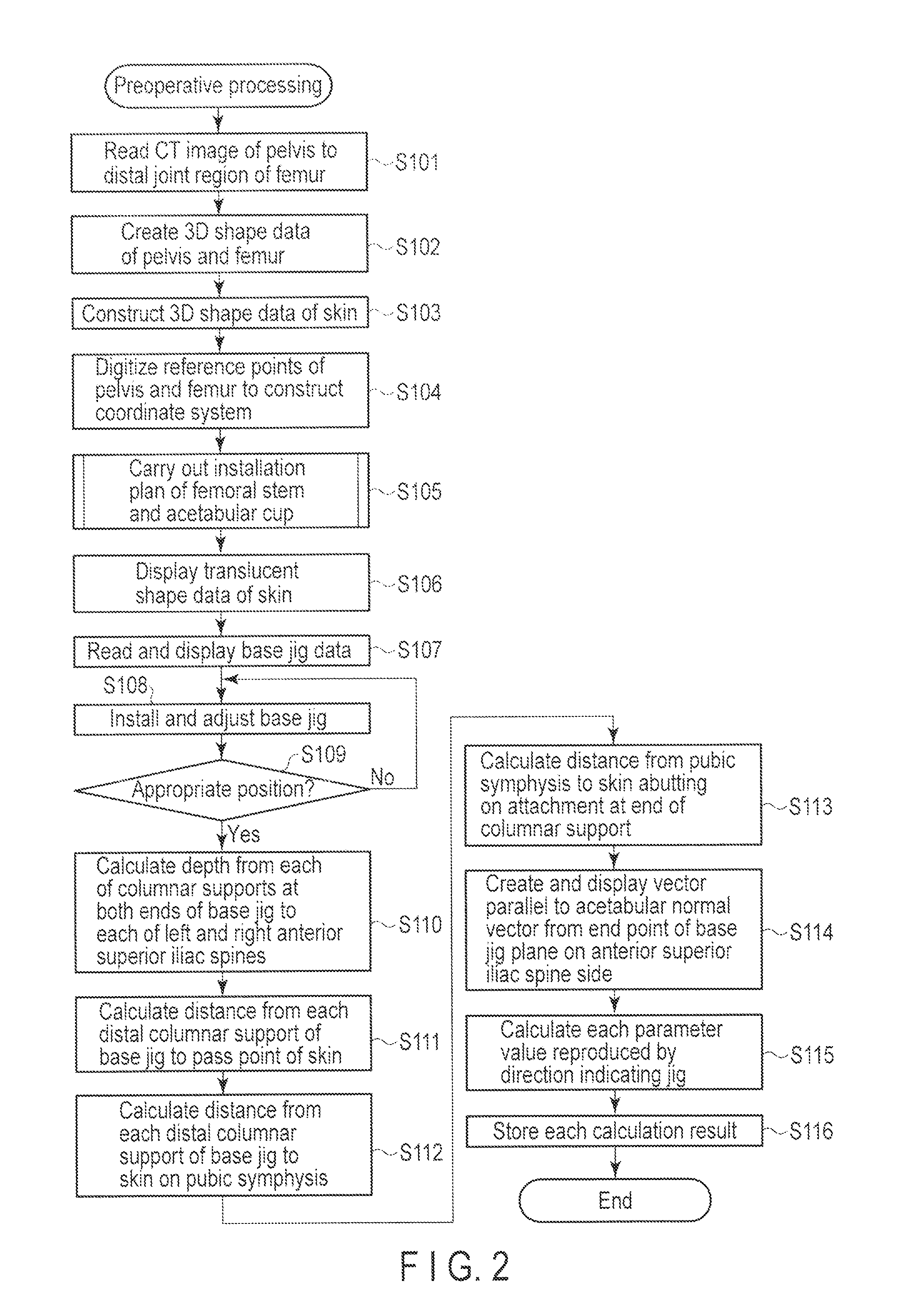
According to one embodiment, a preoperative planning method performed by a computer for hip replacement arthroplasty, includes a base jig setting step of setting a three-dimensional image of a base jig having three or more columnar supports which abut on three or more reference points of the pelvis with respect to the three-dimensional image of the pelvis obtained at the image reconstruction step, and a parameter acquisition step of parameterizing and acquiring a direction of an indicator which runs through a predetermined position on the base jig in the three-dimensional image of the base jig set at the base jig setting step and becomes parallel to the installation direction of the joint prostheses determined at the joint prostheses determination step.

Description

CROSS REFERENCE TO RELATED APPLICATIONS[0001]This application is a Continuation Application of PCT Application No. PCT / JP2010 / 070931, filed Nov. 24, 2010 and based upon and claiming the benefit of priority from prior Japanese Patent Application No. 2009-266649, filed Nov. 24, 2009, the entire contents of which are incorporated herein by reference.BACKGROUND OF THE INVENTION[0002]1. Field of the Invention[0003]The present invention relates to a preoperative planning program and an operation support jig for hip replacement arthroplasty using a data processing apparatus such as a personal computer.[0004]2. Description of the Related Art[0005]A knee joint or a hip joint constituting a part of human lower extremities is a particularly important joint for walking and others in daily life. Because of such a high requirement, such a joint is a region which is apt to suffer a traumatic injury, has a joint cartilage that is subjected to degenerative destruction with aging, and is often led to...

Claims


Application Information

Patent Timeline
Patent Type & Authority Patents(United States)
IPC IPC(8): G06K9/00A61B34/10A61B90/00
CPCA61F2002/4633A61F2/32A61B17/1746A61B2019/505A61B19/50A61B17/58A61B2019/504A61F2/4609A61B2034/104A61B34/10A61B2034/105A61B17/8066A61F2002/4663A61B2034/107
Inventor ITO, TOMOYUKISUDA, KEN
Owner LEXI CO LTD
Learn More