
Internal combustion engine and method for producing such an engine

a combustion engine and internal combustion technology, applied in the direction of machines/engines, mechanical equipment, auxiliaries, etc., can solve the problems of small number of parts and keep the total cost within narrow limits, and achieve the effect of low cost, low weight of internal combustion engines, and high functional integration

Active Publication Date: 2014-10-07
DAIMLER AG
View PDF9 Cites 2 Cited by
  • Summary
  • Abstract
  • Description
  • Claims
  • Application Information

AI Technical Summary

Benefits of technology

[0007]In comparison to standard combustion engines, it is thus possible to dispense with a flange surface requiring sealing between the cylinder head and a cylinder head cover as well as with the cylinder head cover itself. The combustion engine according to the invention thus has a low level of complexity, which keeps the production effort and thus the costs thereof low. It furthermore has only a small number of parts, which also contributes to the low costs. Because the flange surfaces for sealing the cylinder head and the cylinder head cover are integrated into the inlet flange surface and into the outlet flange surface, the effort for sealing the internal combustion engine as well as the effort for installing head cover can be considered as minor, which further contributes to keeping the total costs within narrow limits. Furthermore, the internal combustion engine of the invention is particularly process reliable and can therefore be produced economically.
[0019]The sliders can be in the form of steel dies which further reduces the costs for manufacturing the combustion engine. Sand core shooting is therefore not necessary. The dies and the support are also less sensitive to tolerances than is the case with a sand core support. This enables the forming of very thin wall thicknesses, which entails a lighter weight and lower material costs in the production of the internal combustion engine. This furthermore leads to a particularly high process reliability of the method, which means an additional cost reduction.

Problems solved by technology

It furthermore has only a small number of parts, which also contributes to the low costs.
Because the flange surfaces for sealing the cylinder head and the cylinder head cover are integrated into the inlet flange surface and into the outlet flange surface, the effort for sealing the internal combustion engine as well as the effort for installing head cover can be considered as minor, which further contributes to keeping the total costs within narrow limits.

Method used


Image

  • Internal combustion engine and method for producing such an engine
  • Internal combustion engine and method for producing such an engine
  • Internal combustion engine and method for producing such an engine

Examples


Embodiment Construction

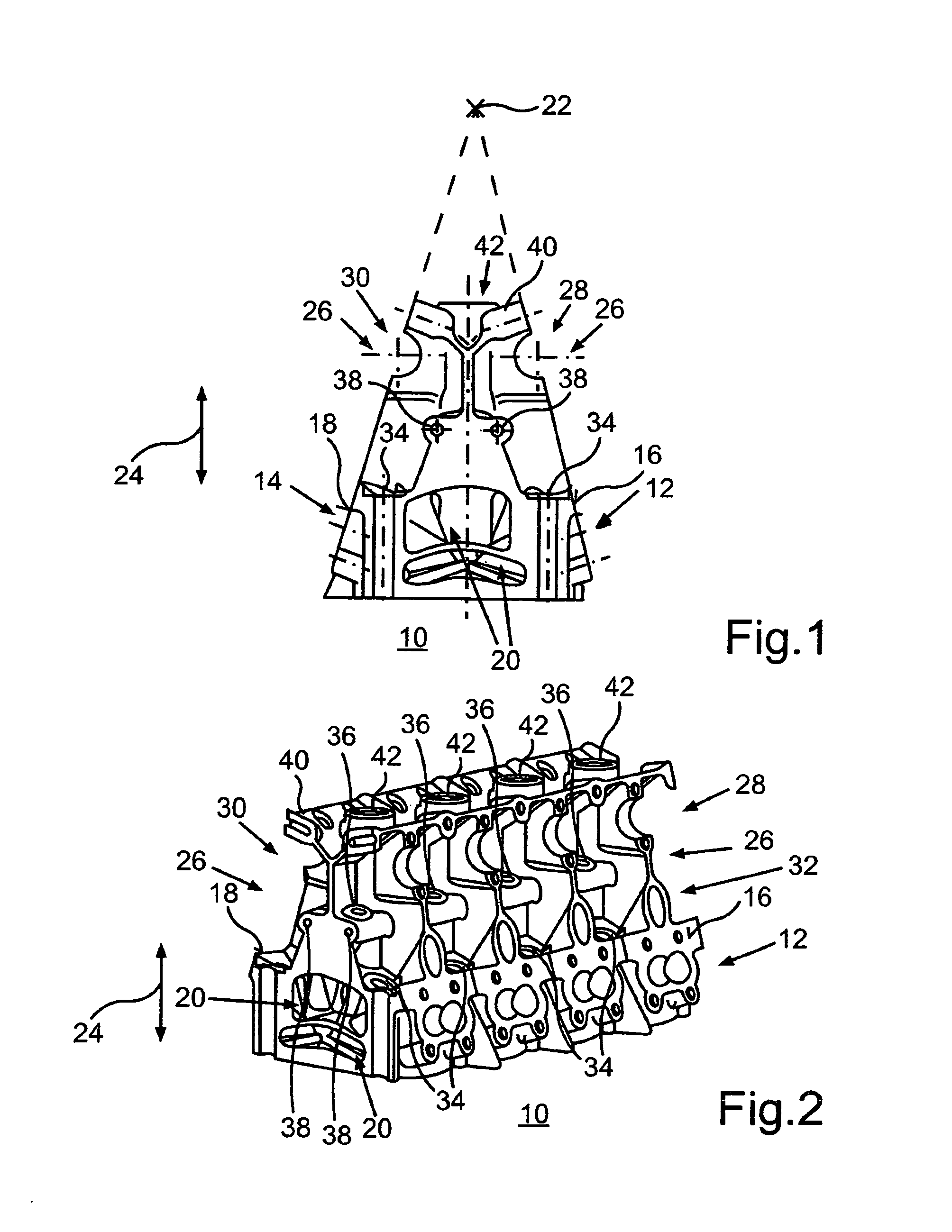
[0024]FIGS. 1 and 2 show a cylinder head 10 for a combustion engine with a plurality of cylinders. The cylinder head 10 has inlet channels 12 via which air or a fuel-air mix can flow into the cylinders of the combustion engine. The cylinder head 10 furthermore has outlet channels 14 via which exhaust resulting from the combustion of the air mixed with fuel in the cylinders or the air-exhaust mix is able to flow out of the cylinders. As can be discerned in FIG. 1 in particular, the inlet channels 12 open at a planar inlet flange-side cylinder head surface 16 and the outlet channels 14 open at a planar outlet flange-side cylinder head surface18 arranged opposite the Inlet flange surface 16. The cylinder head 10 further includes a chamber which accommodates the inlet channels 12 and the outlet channels 14 as well as a coolant chamber 20. The coolant chamber 20 is also designated as a water chamber in which coolant is present, especially during the operation of the internal combustion e...


PUM

PropertyMeasurementUnit
angleaaaaaaaaaa
weightaaaaaaaaaa
temperatureaaaaaaaaaa

Abstract

In an internal combustion engine comprising a plurality of cylinders with at least one cylinder head including inlet channels extending from an inlet flange surface to a cylinder inlet and outlet channels extending from a cylinder outlet to an opening in an outlet flange surface and an oil chamber provided in the cylinder head for supplying lubricant to an actuation device for gas exchange valves, the inlet flange and the outlet flange have flat surfaces which are arranged at an angle relatively to each other so that the surface planes intersect above the cylinder head and the cylinder head, as a result, has an essentially triangular cross-section.

Description

[0001]This is a Continuation-In-Part application of pending international patent application PCT / EP2010 / 006291 filed Oct. 14, 2010 and claiming as the priority date of German patent application.BACKGROUND OF THE INVENTION[0002]The invention relates to an internal combustion engine with an oil chamber formed in the cylinder head for the lubrication of cylinder head components and to a method for producing such an engine.[0003]Internal combustion engines with a plurality of cylinders and at least one cylinder head are well and produced in large numbers. They include cylinder heads with inlet channels which open to an inlet flange surface and outlet channels which open to an oppositely arranged outlet flange surface. Furthermore, an oil chamber may be provided for lubricating the actuation device for gas exchange valves and also a coolant chamber for cooling the cylinder head.[0004]The conventional combustion engines have a relatively high level of complexity, especially in terms of th...

Claims


Application Information

Patent Timeline
Patent Type & Authority Patents(United States)
IPC IPC(8): F01L1/053F01L1/047F01M11/02F01M9/10
CPCF01M9/102F01M9/101F01M11/02F02F7/006F01L1/047F01L1/053F01M9/10F02F1/42Y10T29/49231F01L2001/0537
Inventor HAEFNER, JOCHEN
Owner DAIMLER AG
Learn More