
Ground anchor

Active Publication Date: 2014-09-30
FIXDIRT
View PDF33 Cites 27 Cited by
  • Summary
  • Abstract
  • Description
  • Claims
  • Application Information

AI Technical Summary

Benefits of technology

The present invention is an improved anchor that has cutting bits strategically positioned to allow it to cut through rock during installation. This ensures that the anchor will be able to support the load of the structure. The invention also aims to eliminate broken ground anchors that are sheared due to the stress placed upon the anchor shaft while attempting to drill through rock without cutting tips. Additionally, the invention provides an inexpensive improvement to ground anchors for use in ground that has a likelihood of the presence of rock.

Problems solved by technology

Obstructions in the ground, such as a rock, can stress and shear the shaft or helix.
In the event that a rock formation is quite large, moving the drilling location may not be a viable option.
Another option could be predrilling a hole in the rock but in larger applications this would be costly and unfeasible.
Presently there lacks a helical screw anchors system that is effective in all underground applications.
Even helical screw anchors with sharp curved leading edges are not suitable for cutting through solid rock.
The edges easily become dull and therefore cannot auger through solid immovable rock.

Method used


Image

  • Ground anchor
  • Ground anchor
  • Ground anchor

Examples


Embodiment Construction

[0030]While the present invention is susceptible of embodiment in various forms, there is shown in the drawings and will hereinafter be described a presently preferred, albeit not limiting, embodiment with the understanding that the present disclosure is to be considered an exemplification of the present invention and is not intended to limit the invention to the specific embodiments illustrated.

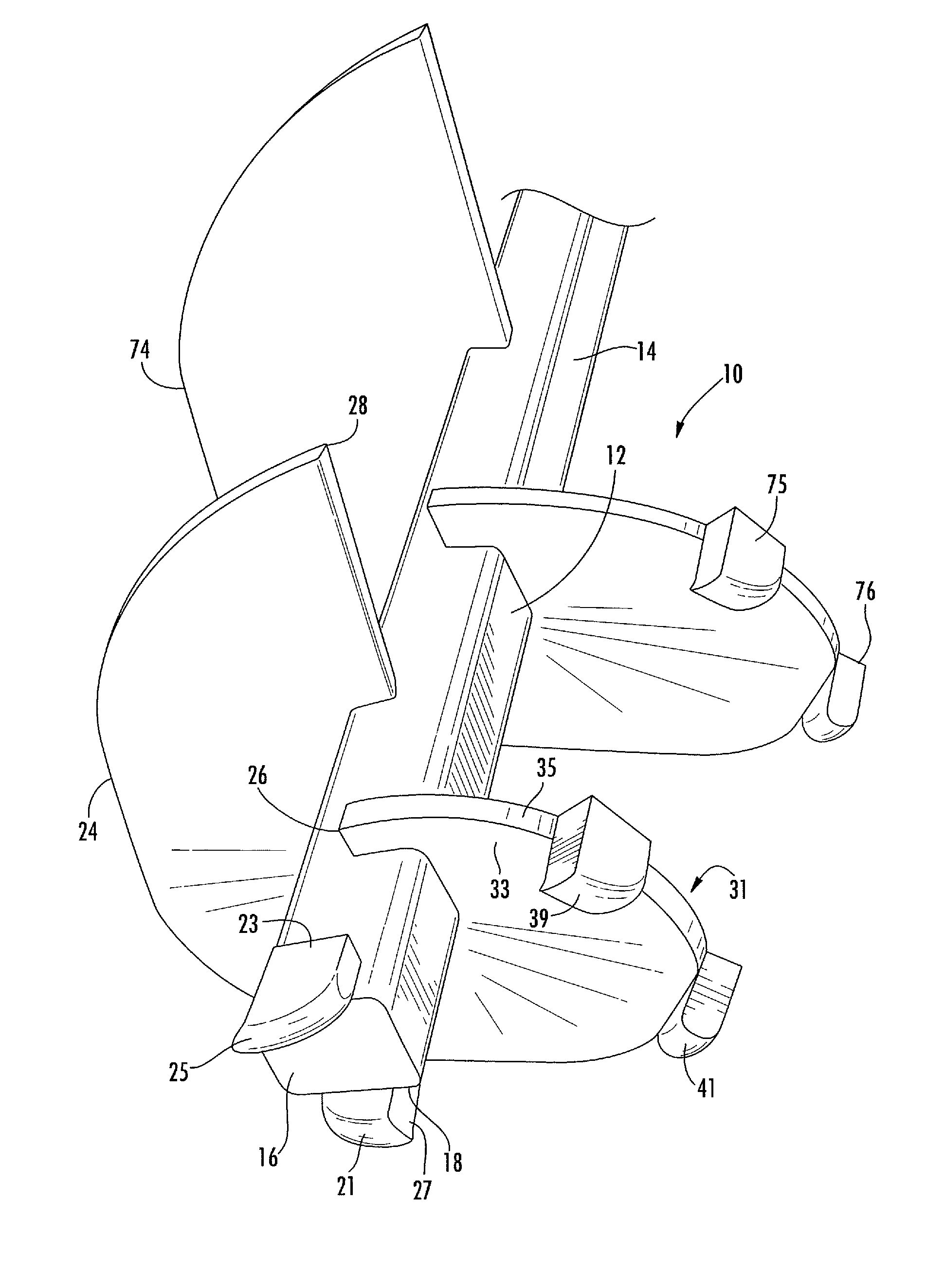
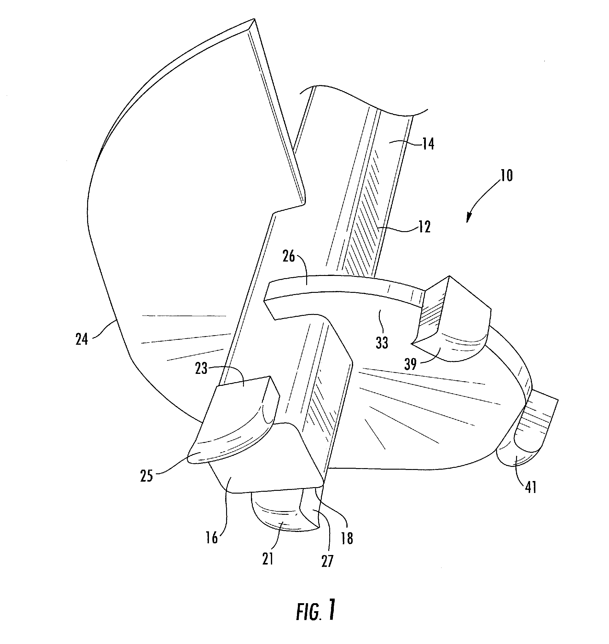
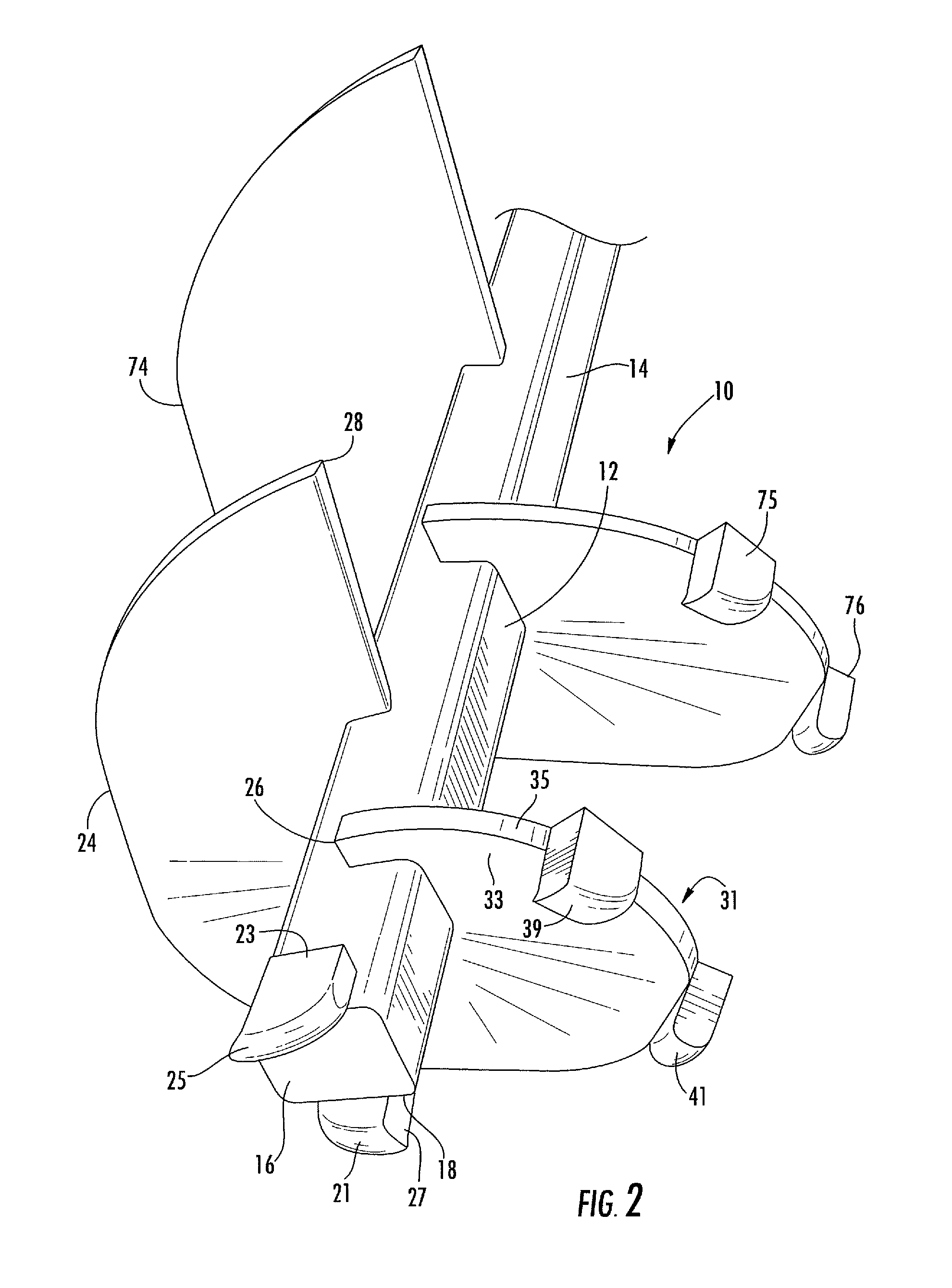
[0031]Now referring to the figures, which illustrate the present invention and the manner in which it is used with like components numbered consistently throughout. A ground anchor assembly with a leading section cutting device 10 is comprised of a shaft member 12 having a longitudinal axis that extends longitudinally and thereby defines an axis of rotation. The shaft includes a proximate end 14 and distal end 16. The shaft member 12 can be of a substantially rectangular or substantially cylindrical shape. The proximate end 14 is constructed and arranged for attachment of a driving mechanism...


PUM


Abstract

A cutting device for use with installation of helical ground anchors designed to cut through rock. The invention has carbide steel cutting tips attached to the distal end of a shaft extending below the end in order to make a first cut through rock along the axis of rotation of the shaft. Helically shaped plates are attached to the shaft at a distance above the shaft set of cutting tips. Attached along the outer edge of the helix are additional carbide steel cutting tips that extend below the bottom surface of the helix and cut along the axis of rotation of the shaft. The present invention allows for the installation of helical ground anchor supports at proper depths without deviation, in situations where the path is obstructed by rock or other hard materials.

Description

PRIORITY CLAIM[0001]In accordance with 37 C.F.R. 1.76, a claim of priority is included in an Application Data Sheet filed concurrently herewith. Accordingly, the present invention claims priority to U.S. Provisional Patent Application No. 61 / 765,472, entitled “GROUND ANCHOR”, filed Feb. 15, 2013. The contents of which the above referenced application is incorporated herein by reference.FIELD OF THE INVENTION[0002]The present invention relates generally to load bearing ground anchors and, more particularly, to an improved ground anchor having cutting bits positioned to cut through solid materials such as bedrock.BACKGROUND OF THE INVENTION[0003]Helical screw anchors are used extensively in construction to transfer loads from structures to the ground. The helical screw anchors must be installed parallel to the direction of pull or push from the load. Anchors are configured to auger into the ground providing a base for both compression and tension applications.[0004]Loose to medium den...

Claims


Application Information

Patent Timeline
IPC IPC(8): E21D20/00
CPCE21D20/00E02D5/801E21B10/44
Inventor DOSDOURIAN, SAMUEL S.DOSDOURIAN, PATRICIA A.
Owner FIXDIRT
Learn More