
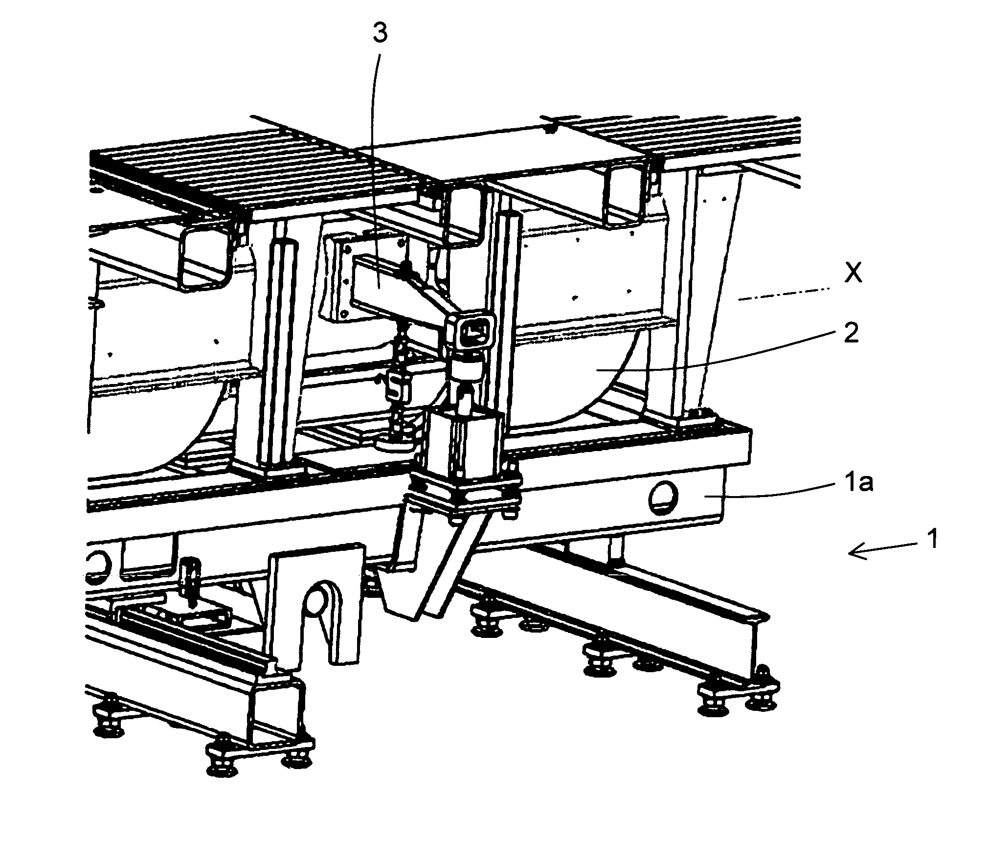
Test stand with an apparatus for calibrating a force-measuring device

a force-measuring device and test stand technology, applied in the direction of measuring devices, instruments, weighing apparatus, etc., can solve the problems of affecting or distorted calibration results, and considerable additional technical effort, so as to improve the calibrating results and reduce the technical effort

Inactive Publication Date: 2014-09-23
HORIBA EURO
View PDF10 Cites 2 Cited by
  • Summary
  • Abstract
  • Description
  • Claims
  • Application Information

AI Technical Summary

Benefits of technology

The invention provides a test stand with an improved calibrating device for measuring force. The stand includes a lever arm and a force-measuring device, which can accurately determine the force exerted by the lever arm. The stand also includes a reference force-generating device and a reference force-transmission device, which can be positioned close to the force-measuring device without the need for an additional lever arm. A thin piece of foil can be used to accurately determine the effective length of the lever arm. The technical effects of this invention are an improved calibration accuracy, minimal technical effort, and reliable transmission of the reference force.

Problems solved by technology

In the case of the calibrating apparatuses known from the state of the art, a considerable additional technical effort, e.g., in the form of additional lever arms, is required in each case.
In addition, it is possible for the load device to be lifted out of its supports due to unsuitable force introduction, whereby the calibrating result can be impacted or distorted, respectively.

Method used


Image

  • Test stand with an apparatus for calibrating a force-measuring device
  • Test stand with an apparatus for calibrating a force-measuring device
  • Test stand with an apparatus for calibrating a force-measuring device

Examples


Embodiment Construction

[0052]As required, detailed embodiments of the present invention are disclosed herein; however, it is to be understood that the disclosed embodiments are merely exemplary of the invention, which can be embodied in various forms. Therefore, specific structural and functional details disclosed herein are not to be interpreted as limiting, but merely as a basis for the claims and as a representative basis for teaching one skilled in the art to variously employ the present invention in virtually any appropriately detailed structure. Further, the terms and phrases used herein are not intended to be limiting; but rather, to provide an understandable description of the invention. While the specification concludes with claims defining the features of the invention that are regarded as novel, it is believed that the invention will be better understood from a consideration of the following description in conjunction with the drawing figures, in which like reference numerals are carried forwar...


PUM

PropertyMeasurementUnit
force-aaaaaaaaaa
forceaaaaaaaaaa
areaaaaaaaaaaa

Abstract

A test stand encompasses a dynamometer, which is supported to oscillate about a main axis, from which a lever arm extends perpendicularly. For calibrating a force-measuring device, which is coupled to the lever arm, provision is made for a pneumatic cylinder as reference force-generating device. The reference force can be measured by a load cell and can be applied to the lever arm via a yoke. The force-measuring device, which is to be calibrated, the pneumatic cylinder, the load cell, and the yoke are disposed on the same side of the dynamometer and act on the same lever arm.

Description

CROSS-REFERENCE TO RELATED APPLICATIONS[0001]This is a continuing application, under 35 U.S.C. §120, of copending International Application No. PCT / EP2010 / 002953, filed May 12, 2010, which designated the United States and was not published in English; this application also claims the priority, under 35 U.S.C. §119, of German Patent Application No. 10 2009 035 410.7, filed Jul. 31, 2009; the prior applications are herewith incorporated by reference in their entirety.STATEMENT REGARDING FEDERALLY SPONSORED RESEARCH OR DEVELOPMENT[0002]Not ApplicableFIELD OF THE INVENTION[0003]The invention relates to a calibrating method for a test stand as well as to a test stand comprising an apparatus for calibrating a force-measuring device.BACKGROUND OF THE INVENTION[0004]Such test stands, e.g., vehicle, engine or transmission test stands, are used by the automobile industry, among others, and support research and development with the help of functional tests, endurance trials for the mechanical ...

Claims


Application Information

Patent Timeline
Patent Type & Authority Patents(United States)
IPC IPC(8): G01L25/00
CPCG01L25/00
Inventor BORMANN, JENSPATSCHKE, KLAUSKUNNE, KAI
Owner HORIBA EURO
Learn More