
Apparatus and method for transmitting/receiving data in a communication system

a communication system and data technology, applied in the field of communication systems, can solve the problems of large limitations, inability to receive service data, and sensitive service delays of real-time services such as voice over internet protocol (voip) or gaming services, and achieve the effect of reducing data loss

Inactive Publication Date: 2014-09-16
SAMSUNG ELECTRONICS CO LTD
View PDF5 Cites 4 Cited by
  • Summary
  • Abstract
  • Description
  • Claims
  • Application Information

AI Technical Summary

Benefits of technology

This approach reduces data loss, decreases error probability, and minimizes handover delays by ensuring reliable data reception and faster handover negotiations, thereby enhancing the overall performance of communication systems for real-time services.

Problems solved by technology

Among the services, real-time services such as Voice over Internet Protocol (VoIP) or gaming service are sensitive to service delay and thus have large limitations.
Especially when a mobile station in a handover zone receives a voice packet service or a gaming service from a base station, it may not receive service data because it is in a poor channel status.
As described above, when the mobile station is in the handover zone, there is a high probability that errors occur during data transmission / reception, resulting in data loss.
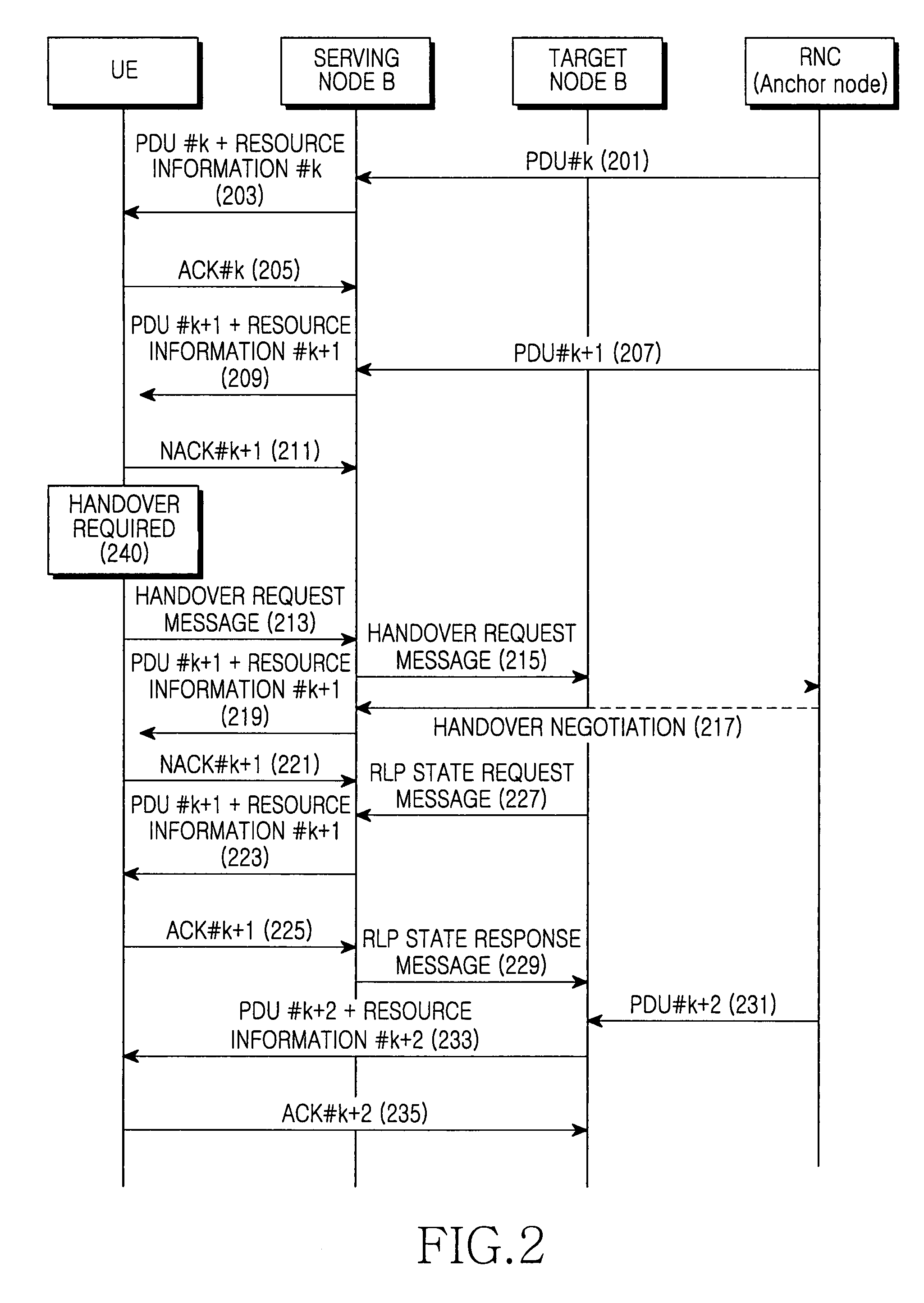
As described above, when the UE is located in the handover zone, it is placed in a poor channel status or affected by neighbor cell interference.
Hence, the handover procedure takes a long time.
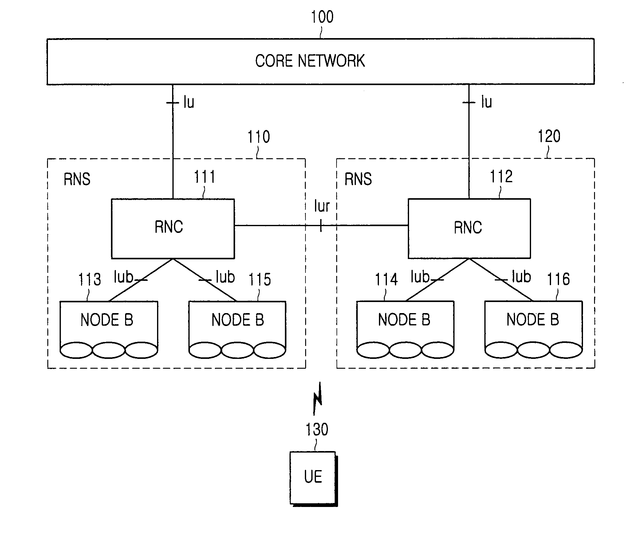
As a consequence, the handover procedure takes much time, and additional transmission of PDU #k+1 from the RNC to the target Node B and additional transmission of PDU #k+1 from the target Node B to the UE involving coding and modulation further increase the handover time and a transmission delay considerably.
As described above, when the UE is in the handover zone, there is a high probability of data loss during data transmission from the serving Node B to the UE.
However, there is no specified method for preventing unnecessary data retransmission.

Method used


Image

  • Apparatus and method for transmitting/receiving data in a communication system
  • Apparatus and method for transmitting/receiving data in a communication system
  • Apparatus and method for transmitting/receiving data in a communication system

Examples


Embodiment Construction

[0039]FIG. 3, discussed below, and the various embodiments used to describe the principles of the present disclosure in this patent document are by way of illustration only and should not be construed in any way to limit the scope of the disclosure. Those skilled in the art will understand that the principles of the present disclosure may be implemented in any suitably arranged communication system.

[0040]Exemplary embodiments of the present invention provide an apparatus and method for transmitting and receiving data by controlling a modulation and coding scheme (MCS) level in a communication system. The exemplary embodiments of the present invention provide an apparatus and method for transmitting and receiving data, in which an MCS level is controlled or extra resources are allocated to prevent unnecessary data retransmission during data transmission / reception in a handover zone. Therefore, the handover is performed with an increased reception reliability of data in a user equipme...


PUM


Abstract

An apparatus and method for transmitting and receiving data in a communication system are provided. A serving node includes a transceiver / receiver including an antenna for transmitting and receiving data from at least one of plurality of customer equipments; a control processor responsive to an requesting handover message indicating handover to a target node for transmitting to the target node a sequence number message wherein the sequence number message has successfully received by the customer equipment; a memory for storing data to be transmitted to the customer equipment.

Description

CROSS-REFERENCE TO RELATED APPLICATION(S) AND CLAIM OF PRIORITY[0001]The present application claims the benefit under 35 U.S.C. §119(a) of a Korean Patent Application filed in the Korean Intellectual Property Office on Nov. 17, 2006 and assigned Serial No. 2006-114012, the entire disclosure of which is hereby incorporated by reference.TECHNICAL FIELD OF THE INVENTION[0002]The present invention generally relates to a communication system. More particularly, the present invention relates to an apparatus and method for transmitting / receiving data in a communication systemBACKGROUND OF THE INVENTION[0003]In general, future-generation communication systems are under development to provide data at high rates to mobile stations, ensuring mobility for the mobile stations. They are also able to provide services with a variety of Quality of Service (QoS) requirements to the mobile stations.[0004]Among the services, real-time services such as Voice over Internet Protocol (VoIP) or gaming servi...

Claims


Application Information

Patent Timeline
Patent Type & Authority Patents(United States)
IPC IPC(8): H04W4/00H04W36/00H04W36/02H04W36/08H04W88/08
CPCH04W36/02H04W36/00H04W36/08H04W88/08
Inventor KIM, DONG-HOKWUN, JONG-HYUNG
Owner SAMSUNG ELECTRONICS CO LTD
Learn More