Lightweight portable electric generator with integrated starter/alternator

a portable electric generator and starter technology, applied in the field of electric generators, can solve the problems of reducing the reliability of this type of system, reducing the size and weight of the flywheel, and still lacking full optimization and complete integration

Inactive Publication Date: 2014-09-02
MAINSTREAM ENG
View PDF15 Cites 8 Cited by
  • Summary
  • Abstract
  • Description
  • Claims
  • Application Information

AI Technical Summary

Benefits of technology

[0011]The present invention relates to portable electric power generation equipment where external mechanical power is not required. The internal combustion engine and the flywheel / alternator are designed as an integrated unit and the flywheel / alternator is the only driven mechanism of the engine. Furthermore, circuitry is used so the alternator can function as a motor starter and then switch to an alternator function once the engine starting has been completed. Since the entire winding of the alternator is used during starting, the starting torque capability is much greater than a conventional starter motor. In addition, the starting action can be operated indefinitely without any concern of overheating, as is common with a conventional starter motor. There are also no life limiting or maintenance concerns related to the starter pinion gear getting stuck engaged or disengaged or any wear associated with the mating pinion and ring gears. The overall parts count and therefore the cost of manufacture and the weight of the system are also greatly reduced.
[0015]To integrate the generator alternator and starting functions into the engine flywheel to eliminate excessive components and reduce weight. The new flywheel alternator / starter provides inertia to reduce speed fluctuations, provides a means of cooling both the electrical and mechanical components, and generates electrical power.
[0018]To provide an improved multi-function engine cowling, that not only provides protection from and to the rotating components, but also serves as a fan shroud, a fan scroll (or volute), a coolant distributor (to cool the engine, alternator, and engine oil), an electronic cold plate (for mounting and cooling ac-to-dc power conversion electronics during power generation, dc-to-ac power conversion electronics during motor starting, voltage regulation electronics, current regulation electronics, and / or control electronics), and a coolant duct.

Problems solved by technology

Using a separate alternator coupled to the engine via the protruding crankshaft and a dedicated starter motor mounted on the engine and temporarily coupled to the engine through gear teeth (ring gear) on the flywheel is typically bulky and heavy due to lack of weight optimization and integration.
Furthermore, alternator coupling failures due to misalignment and failure of the starter motor to engage or disengage, as well as gear wear can reduce the reliability of this type of system.
While this configuration provides a size and weight improvement over the first configuration, full optimization and complete integration is still lacking.
Of the magnesium alloys, magnesium-aluminum (AM) and magnesium-aluminum-zinc (AZ) alloys have excellent room temperature strength and / or ductility but do not exhibit good creep resistance.
AE alloys are expensive due to rare-earth additions, have poor die cast properties, have high oxidation rate, and low fatigue resistance.
However, the electric power generated by the alternator is small compared to the mechanical power generated by the shaft.
Those alternators are not designed to utilize all of the mechanical power generated by the engine shaft.
The waste heat is produced due to the inefficiency of the power conversion devices and must be removed for proper operation of the generator.
Finned structures common on existing flywheel / alternators are not able to provide ample cooling to both the engine and the alternator.
Larger power generation creates larger quantities of waste heat that can not be removed by simple paddle style circulators.

Method used


Image

  • Lightweight portable electric generator with integrated starter/alternator
  • Lightweight portable electric generator with integrated starter/alternator
  • Lightweight portable electric generator with integrated starter/alternator

Examples


Embodiment Construction

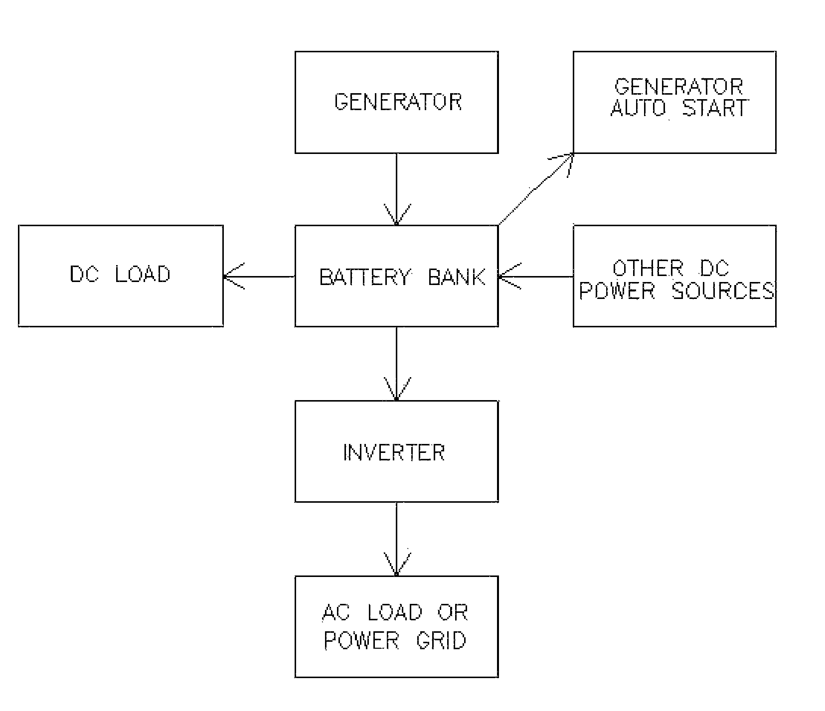
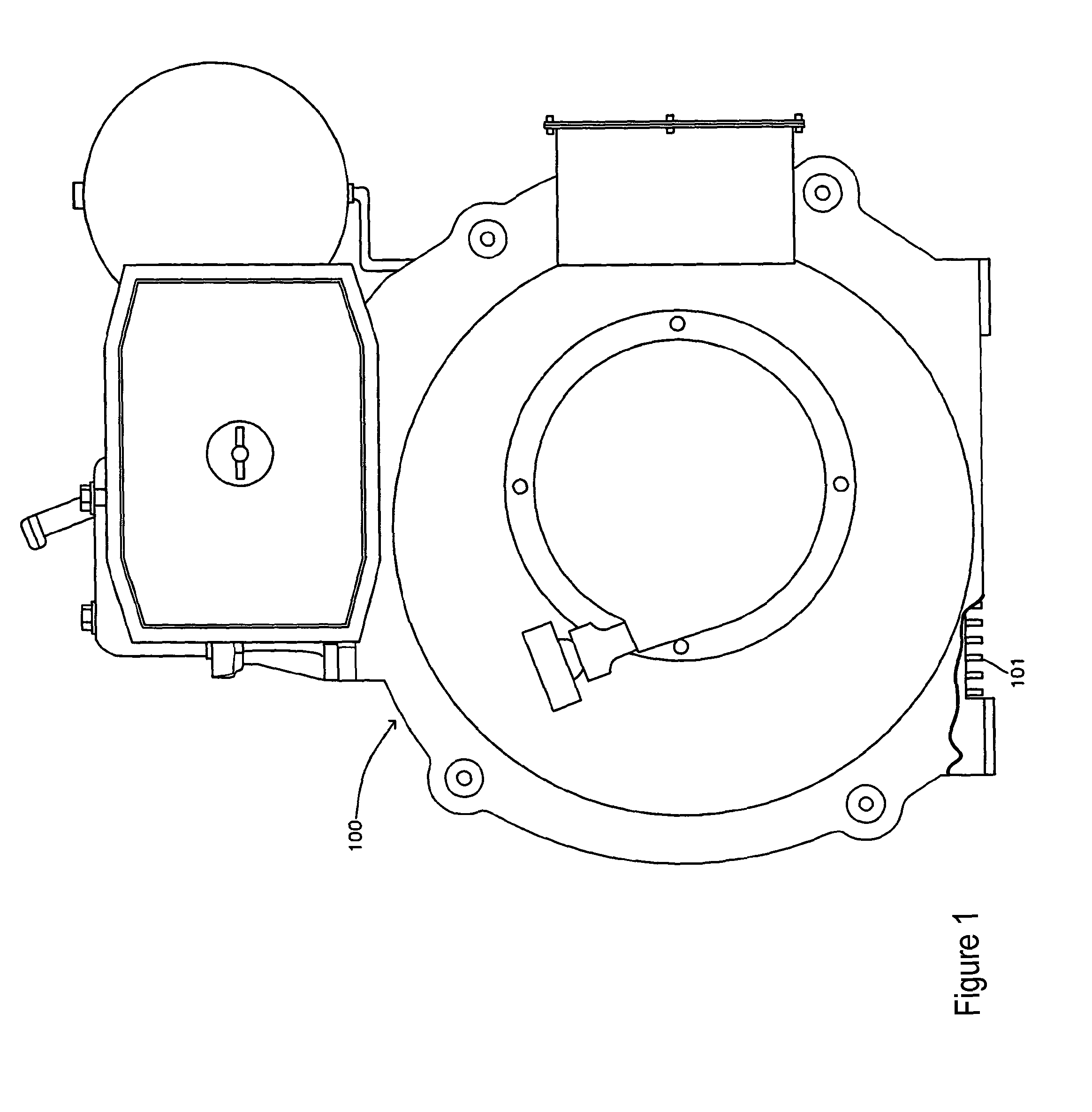
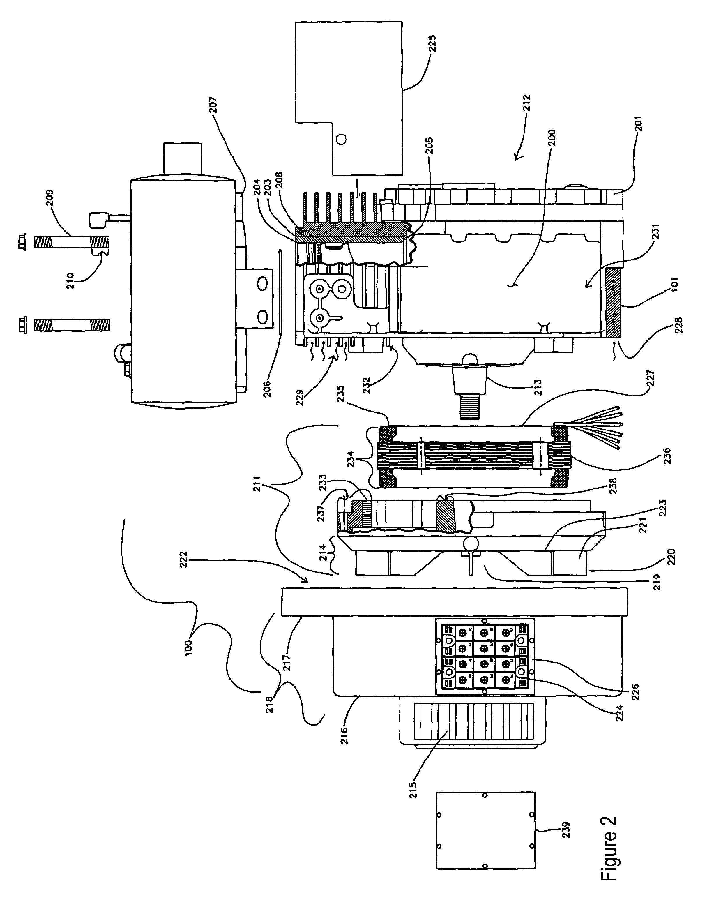
[0031]The present invention relates to portable electric power generation equipment. The internal combustion engine and the alternator / starter are designed as an integrated unit and the alternator / starter is the only driven mechanism of the engine and the only electrical start mechanism on the engine. The engine can be equipped with a manual recoil starter attached to the flywheel alternator / starter if desired. The internal combustion engine in the currently preferred embodiment is of the compression ignition type, although it will be apparent to anyone skilled in the art that the present invention also applies to spark ignition type engines. The following terms are defined to assist with the description of the invention as used the context of the present invention.

[0032]An internal combustion engine (or engine) is a device that generates mechanical power through the combustion of fuel. Compression-ignition engines and spark-ignition engines are types of engines.

[0033]An alternator ...


PUM


Abstract

A compact and lightweight electric generator for portable power applications employs a new engine design and integration approach for reducing engine, generator, and starter weight. A unique flywheel alternator / starter configuration that generates electrical power, rotates the engine for starting, provides inertia for smooth engine operation, pressurized air for cooling, and inertia for the alternator. An engine cowling provides rotating component protection, a fan shroud mechanism, cooling air ducts, and a cooling mechanism for handling large quantities of heat produced by rectified power conversion. An electrical hook up that allows the generator to provide transient surge capacity for starting inductive loads, or improved load leveling and fuel efficiency.

Description

RELATED APPLICATIONS[0001]This application is a continuation-in-part of U.S. application Ser. No. 10 / 649,793, filed Aug. 28, 2003.BACKGROUND OF THE INVENTION[0002]1. Field of the Invention[0003]The present invention relates to electrical generators, particularly, to size, weight, and reliability improvements of portable electric generators. A flywheel starter / alternator mounted on an air-cooled or water-cooled internal combustion engine generates electrical power when the engine is operating and can also be used to provide engine rotation for starting. The electrical configuration provides improved power surge capability and load leveling capability. Improvements in the engine design and the functionality of the integrated flywheel-alternator-starter result in a smaller and lighter generator with fewer components that is easier to transport, more reliable, and may be started in colder ambient conditions.[0004]2. Description of the Related Art[0005]Portable electric generators of the...

Claims


Application Information

Patent Timeline
Patent Type & Authority Patents(United States)
IPC IPC(8): F02N11/08F01M11/00F01P1/02F01P1/06F02B63/04H02K1/27H02K7/18H02K9/06H02K11/04
CPCH02K1/2786H02K11/048H02K9/06H02K7/1815F02B63/04F01M11/0004F05C2201/028F01P1/06F01P1/02F02N11/04F02N11/0866F02N2011/0896F02N3/02H02K11/05H02K1/2791
Inventor COLE, GREGORY S.TEWS, BRIAN E.SCARINGE, ROBERT P.ROTH, ROBERT PAULMASON, DANIEL
Owner MAINSTREAM ENG
Why Eureka
Try Eureka