
Band clamp installation markers

a technology of installation markers and band clamps, which is applied in the direction of hose connections, instruments, chemical indicators, etc., can solve the problems of increased probability of misinstallation and occasionally mis-installation of band clamps, and achieve the effect of shortening the band clamp loop

Inactive Publication Date: 2014-09-02
HONEYWELL INT INC
View PDF12 Cites 4 Cited by
  • Summary
  • Abstract
  • Description
  • Claims
  • Application Information

AI Technical Summary

Benefits of technology

The solution ensures that the band clamp installation is visually verified, reducing the likelihood of mis-installation by providing a clear indication of when the clamp is satisfactorily tightened, enhancing the reliability of the installation process.

Problems solved by technology

Such band clamps can be occasionally mis-installed by simple omission by the installer to tighten them properly.
Probability of mis-installation is increased by the fact that a band clamp installation process does not usually, by itself, generate sufficient visual clues to be able to judge effectiveness of band clamp installation.

Method used


Image

  • Band clamp installation markers
  • Band clamp installation markers
  • Band clamp installation markers

Examples


Embodiment Construction

[0016]The following detailed description is of the best currently contemplated modes of carrying out exemplary embodiments of the invention. The description is not to be taken in a limiting sense, but is made merely for the purpose of illustrating the general principles of the invention, since the scope of the invention is best defined by the appended claims.

[0017]Various inventive features are described below that can each be used independently of one another or in combination with other features.

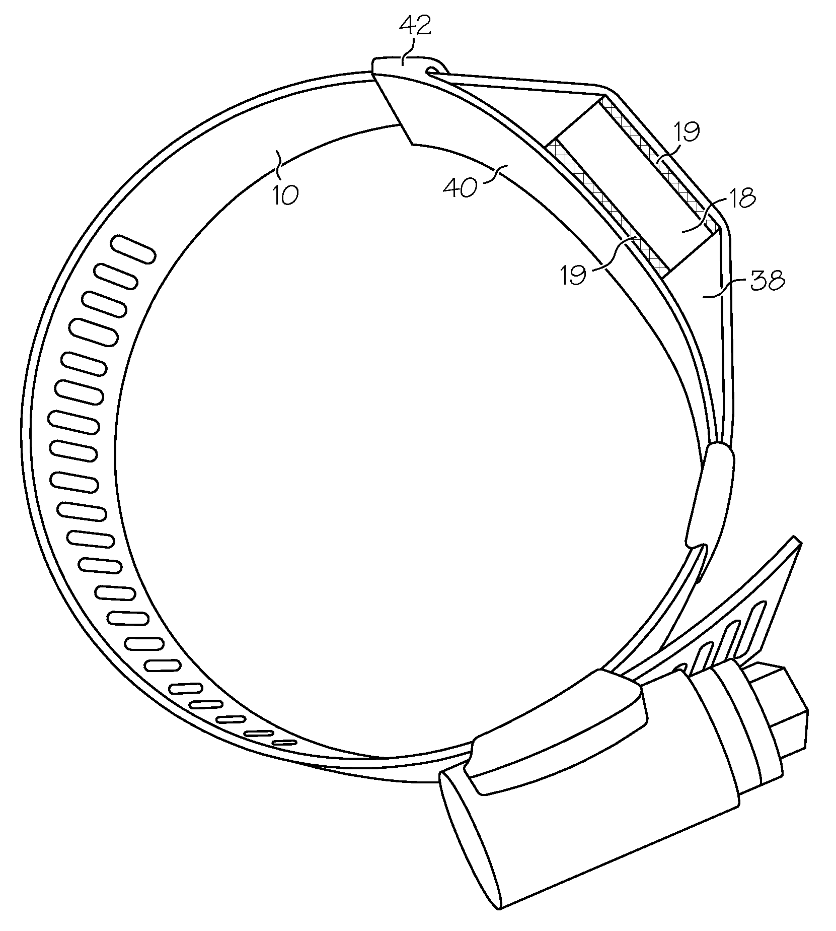
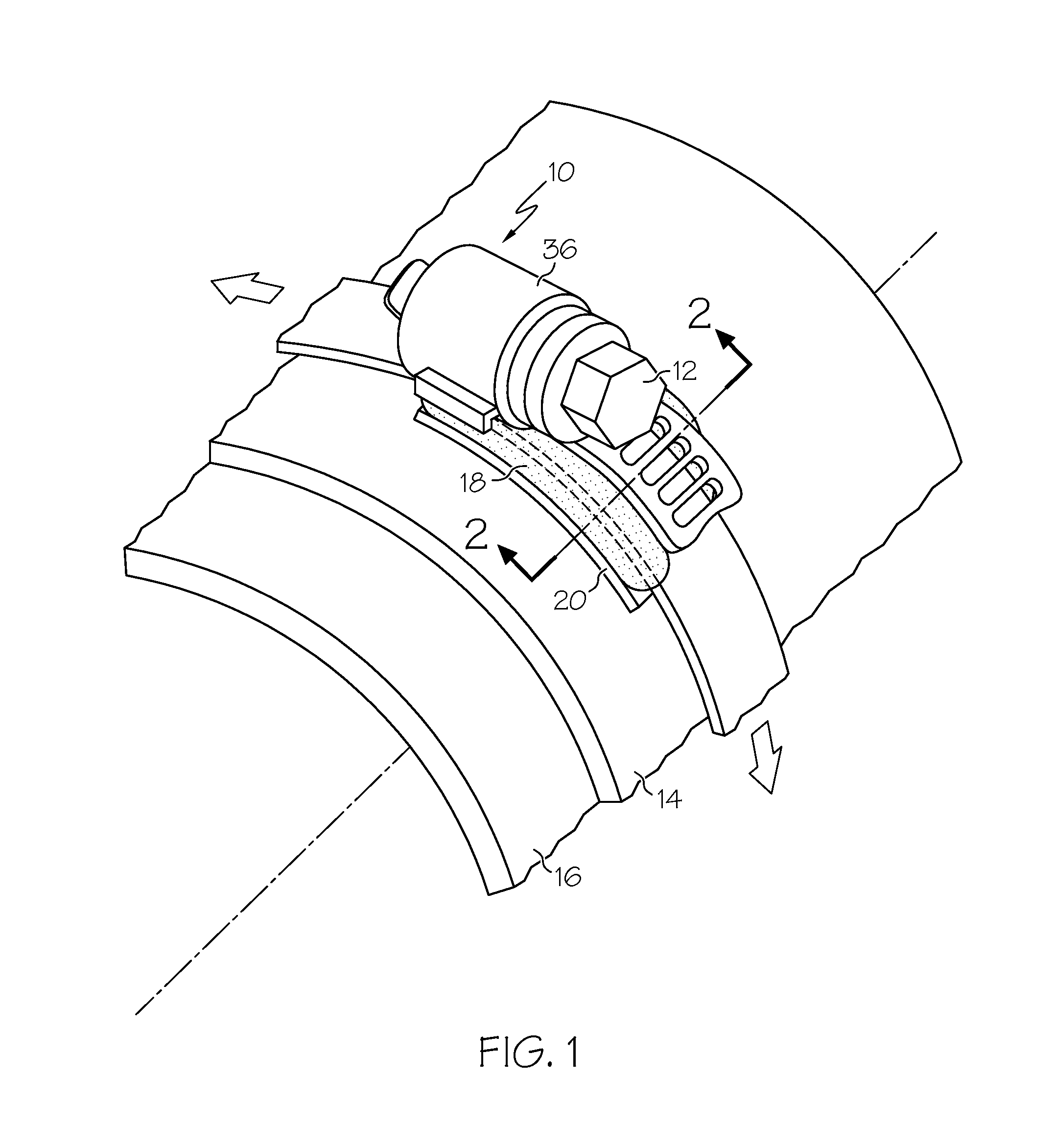
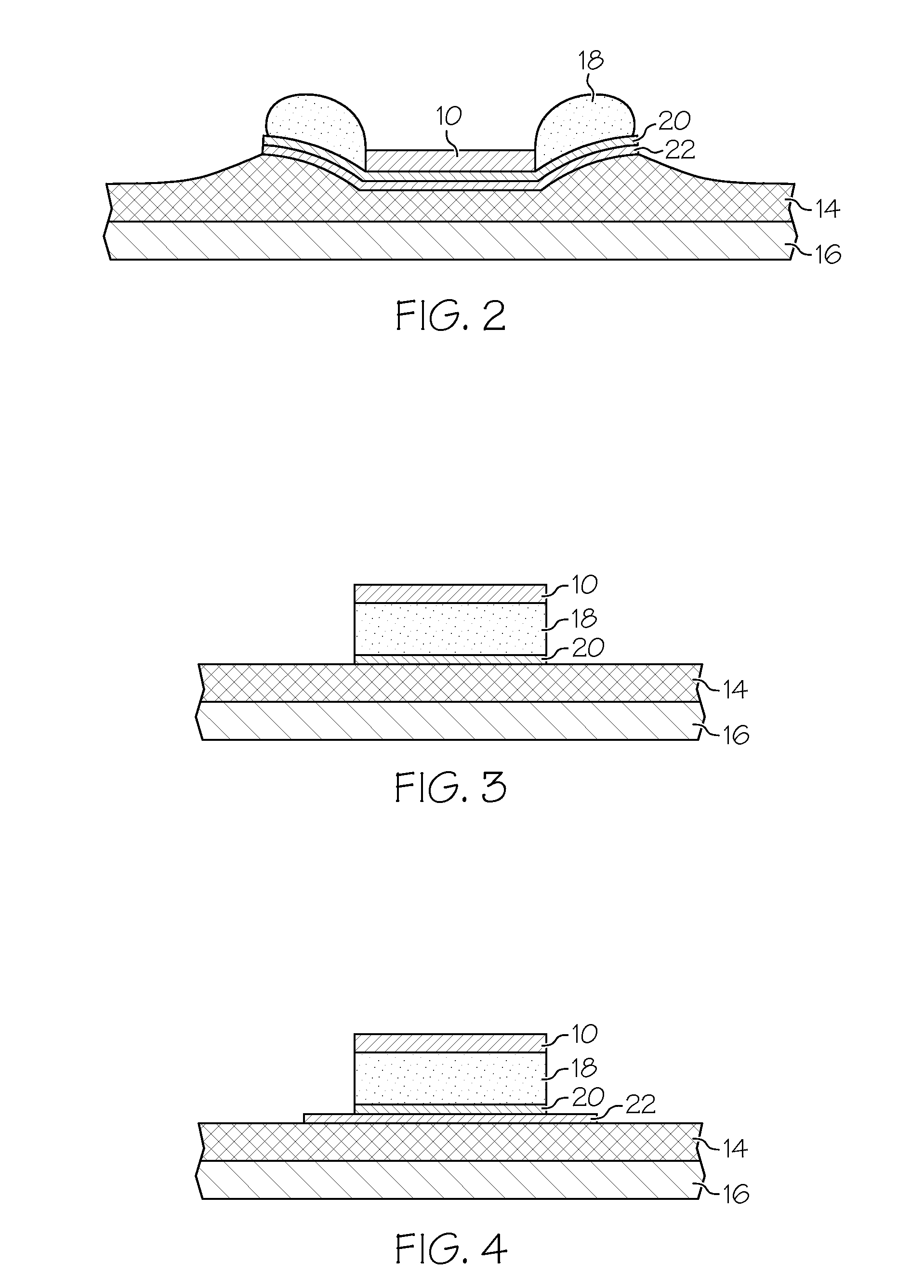
[0018]Broadly, embodiments of the present invention provide a band clamp with an installation marker made of displaceable material placed circumferentially at a strategic visible location, for example at or near the tightening element of a clamp, such as a bolt or another fastening device. The marker is located radially between the band of the clamp and a clamped object such as, for example, a flexible sleeve. The marker is adapted to respond to the state of band constriction about the obj...


PUM

PropertyMeasurementUnit
stretchableaaaaaaaaaa
color contrastaaaaaaaaaa
circumferenceaaaaaaaaaa

Abstract

A band clamp has a band constriction sensing marker adapted so as to gradually visibly respond to the stage and state of the band clamp installation at the object to be secured. Before the band clamp is installed, a displaceable material may be partially or entirely hidden between the band and the securable object, for example flexible sleeve, wherefrom it is forcefully moved by the clamp to the sides during installation. A gradually appearing amount, color and shape of the moved marker material may provide visual clues about band clamp installation. In some embodiments, a contrastingly colored under material wider than the band clamp may be disposed underneath a marker on the side of the object being secured. Due to the band constriction during joint installation, the marker material parts sidewise from underneath the band clamp and masks the contrasting under material with neutrally colored marker material.

Description

BACKGROUND OF THE INVENTION[0001]The present invention relates to band clamps and methods to reliably install such about securable objects. More particularly, the invention is concerned with band clamps having an installation marker for signaling that the band clamp is being and / or has been properly installed.[0002]Band clamps are universal means of affixing tubular and similar products to other components and / or each other. The two most used types of band clamps are a worm gear clamp and a T-bolt clamp. Both of these clamp types use bolts to close and tighten the band loop.[0003]In many cases, directly clamped objects, such as sleeves, are of a flexible hose type. Flexible objects need more clamp band travel to become fully secured. Such band clamps can be occasionally mis-installed by simple omission by the installer to tighten them properly. Probability of mis-installation is increased by the fact that a band clamp installation process does not usually, by itself, generate suffic...

Claims


Application Information

Patent Timeline
Patent Type & Authority Patents(United States)
IPC IPC(8): F16L33/08
CPCF16L33/085F16L2201/10Y10T24/14Y10T24/1431Y10T24/1412Y10T24/1427Y10T29/49764Y10T24/1457
Inventor FIETKIEWICZ, BOGUSLAW, J
Owner HONEYWELL INT INC
Learn More