Micro-mirror system and associated control method

a micro-mirror and control method technology, applied in the field of micro-mirror systems, can solve the problems of multiple compensable systematic errors in actual curves and changes in voltage at the output of sensors, and achieve the effect of increasing image quality

Active Publication Date: 2014-08-19
ROBERT BOSCH GMBH
View PDF3 Cites 0 Cited by
  • Summary
  • Abstract
  • Description
  • Claims
  • Application Information

AI Technical Summary

Benefits of technology

[0018]Information concerning the light intensity which may possibly strike the sensor at a given point in time may be ascertained in advance, since all data necessary for this purpose are already present in the control system for the light module, or are specified by the configuration of the light source relative to the sensor and the design of the sensor. For micro-mirror actuators for imaging, intensity information, for example for the primary colors red, yellow, and blue (RGB), is established for each pixel. These data are usually available in high resolution in digital form, are read into the data field at a high frequency by the processor, and are temporarily present in a buffer memory before being relayed to the driver for the light source (a laser, for example). With the aid of the approach according to the present invention, the pixel information is now synchronized with the control of the micro-mirror module, thus allowing the light dependency of the offset of the sensor to be actively compensated for.
[0019]Accordingly, one aspect of the exemplary embodiments and / or exemplary methods of the present invention is the use of information, known per se, concerning the light intensity, which influences the position of the offset, of a beam to be directed from one or multiple light sources, for example an RGB laser, in order to continuously compensate for the offset or the change in offset of the sensor output voltage in the active state. This results in active compensation of the static light-dependent offset of the sensor by the actual position of the micro-mirror in the X, Y, and Z directions. In addition, active compensation of the dynamic light-dependent offset, whose frequency is in the bandwidth of the evaluation electronics system and which likewise distorts the actual position of the micro-mirror, may also be achieved. Overall, it is thus possible to carry out the position detection and the deflection in a very precise manner, resulting in increased image quality.

Problems solved by technology

If a force is exerted on the mirror for the deflection, this results in a change in voltage at the output of the sensor.
The actual curve has several compensatable systematic errors, such as linearity errors and offset errors, as well as random errors due to instrument-related fluctuations.

Method used


Image

  • Micro-mirror system and associated control method
  • Micro-mirror system and associated control method
  • Micro-mirror system and associated control method

Examples


Embodiment Construction

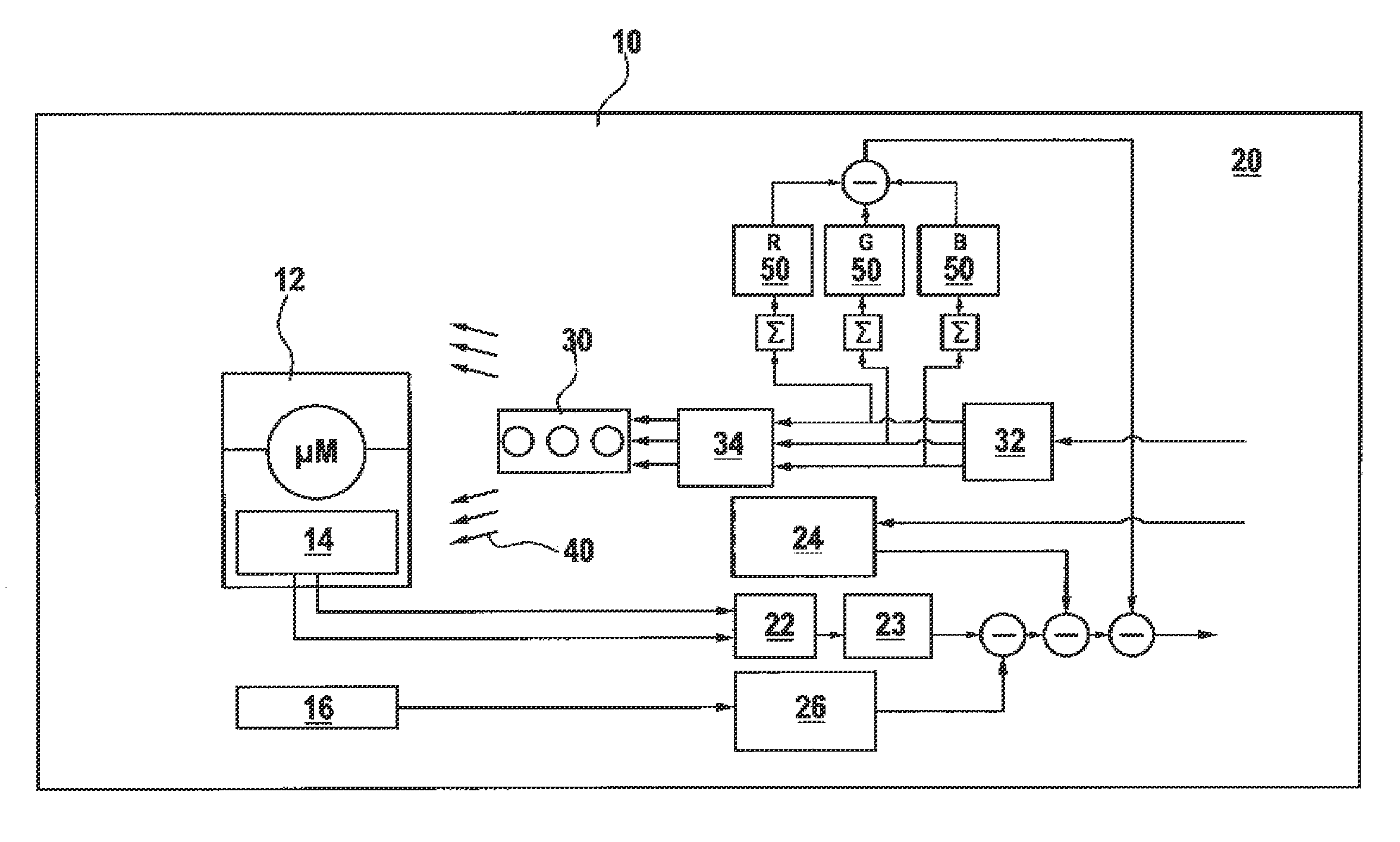
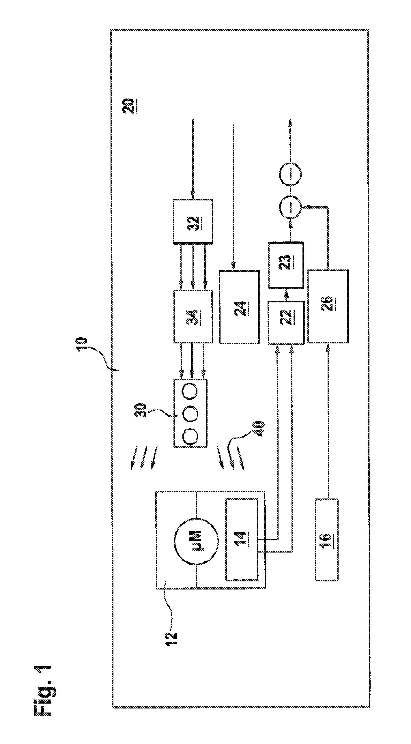
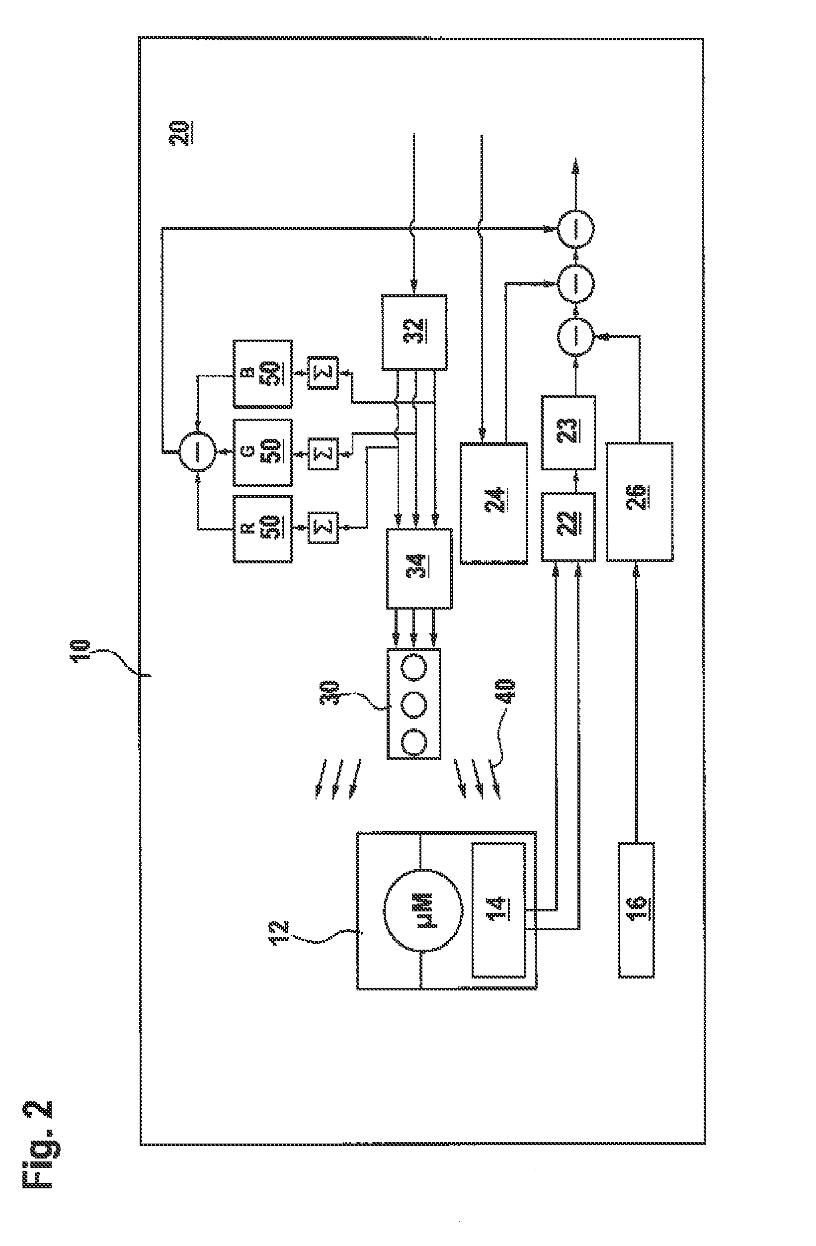
[0028]FIG. 1 shows a micro-mirror system 10 having a micro-mirror module 12 which includes, among other elements, piezoresistive sensors 14 for detecting the relative position. A temperature sensor 16 continuously detects the instantaneous temperature of the position sensor.

[0029]System 10 also includes an evaluation and control unit 20 which is designed to control the micro-mirror actuator contained in micro-mirror module 12. Piezoresistive sensors 14 deliver an output signal, which via electronic filter elements 22, 23 is read into evaluation and control unit 20. A temperature-dependent offset characteristic curve 26 is taken into account for determining an instrument-related offset 24 for the output signal of piezoresistive sensors 14.

[0030]A light source 30, in the present case an RGB laser module, is operated via an independent control unit. A data field is transferred to a buffer memory 32, which in turn provides the data for laser driver 34.

[0031]Micro-mirror system 10 accord...


PUM

PropertyMeasurementUnit
light intensityaaaaaaaaaa
offset voltageaaaaaaaaaa
edge lengthaaaaaaaaaa

Abstract

A micro-mirror system having a micro-mirror actuator, a sensor for detecting the position of the micro-mirror actuator, a light module having at least one light source and an associated control system via which a light intensity of the light source is controllable, and an evaluation and control unit which is designed to control the micro-mirror actuator as a function of an output signal of the sensor. The system provides that the evaluation and control unit includes a compensation routine in which an offset voltage of the output signal of the sensor is settable as a function of the light intensity of the light source to be expected at the point in time that the micro-mirror actuator is activated.

Description

RELATED APPLICATION INFORMATION[0001]The present application claims priority to and the benefit of German patent application No. 10 2011 006 337.4, which was filed in Germany on Mar. 29, 2011, the disclosure of which is incorporated herein by reference.FIELD OF THE INVENTION[0002]The present invention relates to a micro-mirror system, an associated control method, a computer program with which the method may be carried out, and a memory medium which contains the computer program.BACKGROUND INFORMATION[0003]A micro-mirror actuator is a microelectromechanical component for dynamically modulating light. For micro-mirror actuators, a distinction is made between so-called microscanners and spatial light modulators.[0004]In microscanners, a light beam is modulated on a continuously moved individual mirror. Light may be guided or “scanned” over a projection surface with grazing incidence. Microscanners are used in projection displays, bar code scanners, in endoscopy, and in spectroscopy, a...

Claims


Application Information

Patent Timeline
Patent Type & Authority Patents(United States)
IPC IPC(8): G02B26/00G02B26/02G02F1/00
CPCG02B26/0833G09G3/3466G09G2320/041
Inventor DIBS, MOHAMAD IYAD ALWENZLER, AXELKRAYL, OLIVER
Owner ROBERT BOSCH GMBH
Why Eureka
Try Eureka