
Electrical connector with anti-arcing feature

a technology of electrical connectors and anti-arcing, which is applied in the direction of coupling contact members, coupling device connections, coupling bases/cases, etc., can solve the problems of reducing affecting the service burning to users, so as to prolong the useful life of electrical connectors, suppress electrical arcing, and suppress electrical arcing

Active Publication Date: 2014-08-19
ANDERSON POWER PRODS
View PDF44 Cites 5 Cited by
  • Summary
  • Abstract
  • Description
  • Claims
  • Application Information

AI Technical Summary

Benefits of technology

Effectively suppresses arcing between separated contacts during connection and disconnection, protecting users from burns and extending connector lifespan without increasing system bulk or cost.

Problems solved by technology

Electrical arcing between the separated contacts of a live electrical connector present a hazard of fire and of burns to the user, and any such arcing tends to reduce the useful life of the connector.
Nevertheless, due to the fallibility of human nature, it remains true that electrical connectors may at times be inadvertently connected or disconnected while the electrical load is turned on.
However, when the electricity is direct current, the voltage is constant and never zero, and electrical arcing between the separating contacts will be maintained over a substantial range of contact separations, creating a burn hazard for the user and reducing the useful life of the connector.
However, adding an additional contact and switching device increases both the bulk and the cost of the system.
However, in this approach arcing can still occur through an indirect path that by-passes the insulating barrier.

Method used


Image

  • Electrical connector with anti-arcing feature
  • Electrical connector with anti-arcing feature
  • Electrical connector with anti-arcing feature

Examples


Embodiment Construction

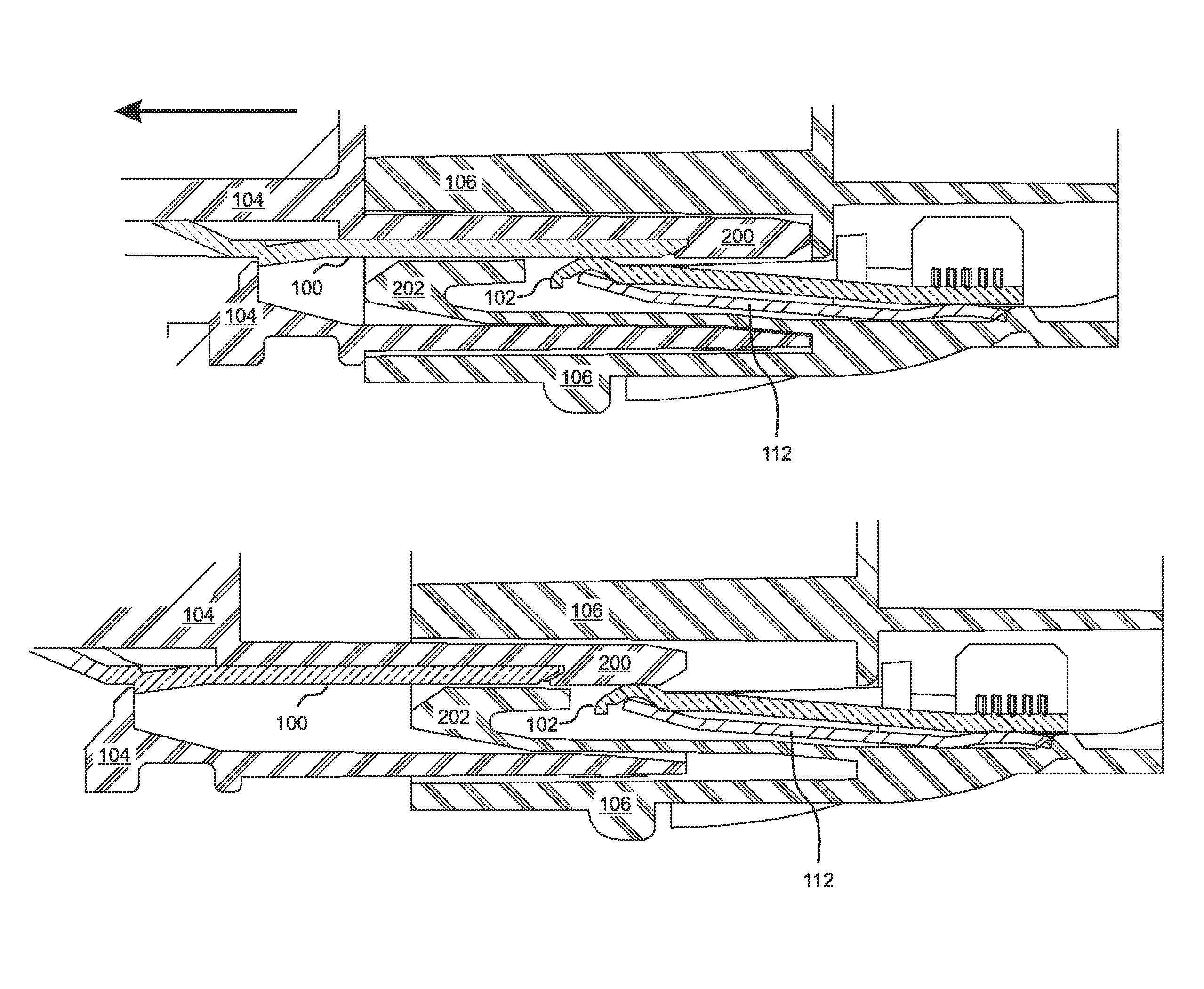
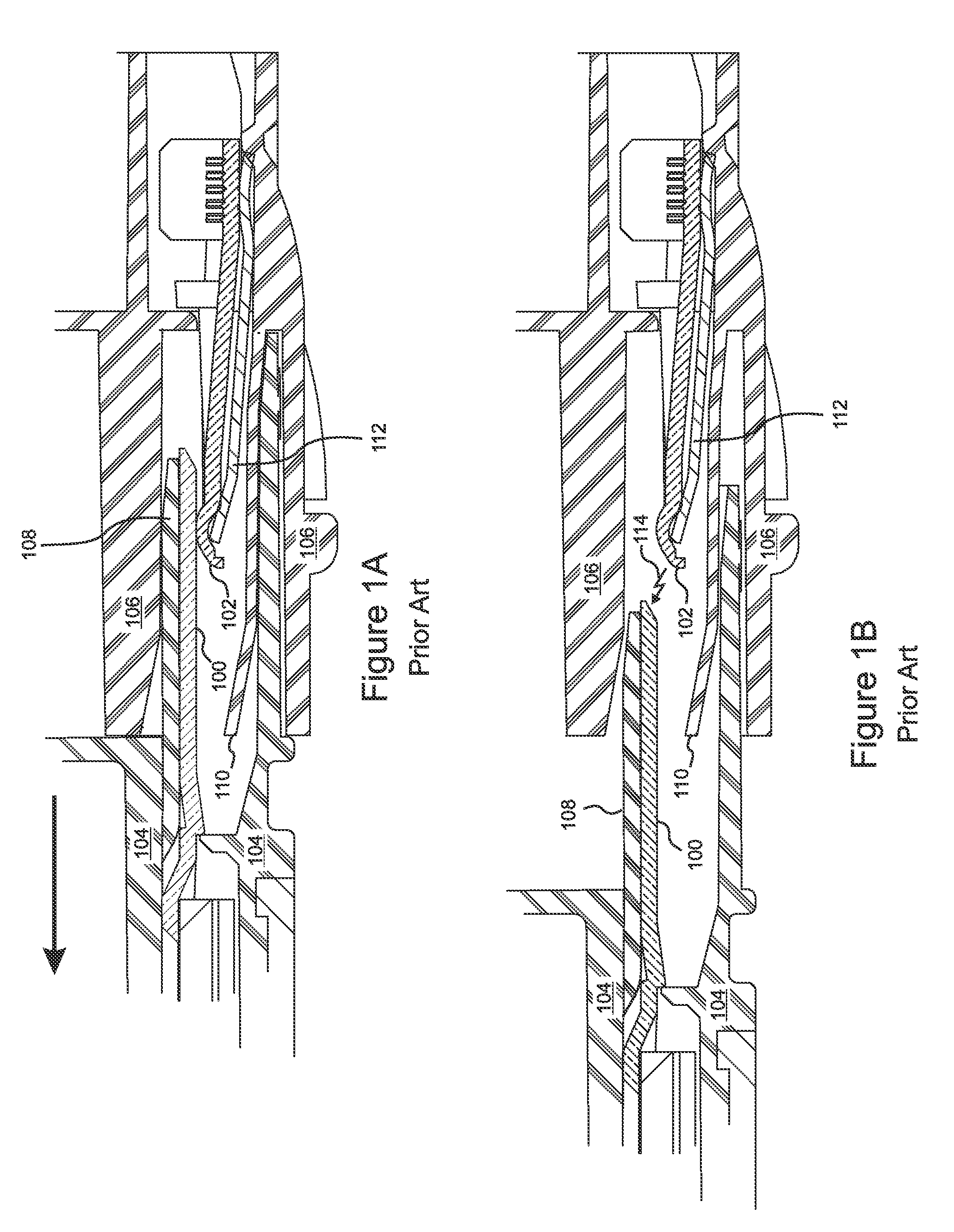
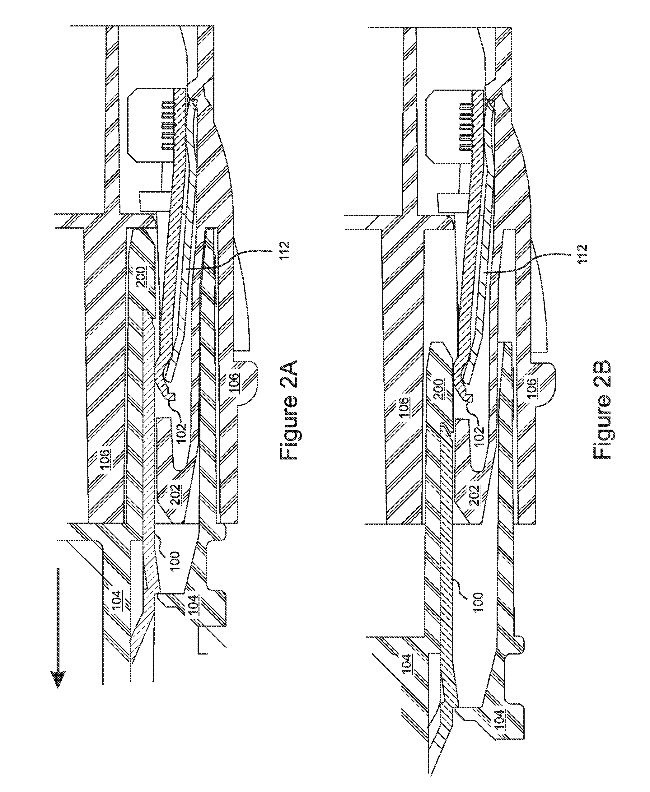
[0022]With reference to FIG. 1A, a typical male and female connector pair of the prior art includes a male contact 100 and a female contact 102. One of the contacts (here the female contact 102) is flexible and is placed under tension by a spring 112 so that a shaped region of the contact 102 will ride over the leading end of the male contact 100 and press against a connecting surface of the male contact 100 when the connectors are mated. Insulated housings 104, 106 surround the male and female contacts, and shield the contacts from environmental hazards, as well as providing some protection to a user in case arcing occurs when the user is handling the connector pair. In the prior art example of FIG. 1A, additional insulating structures 108, 110 are provided proximal to the outer faces of the contacts 100, 102 to support the contacts 100, 102, and to provide receiving channels for the two insulating housings 104, 106 to mate. A spring 112 is also included to provide a pressing tensi...


PUM


Abstract

A novel connector pair suppresses arcing during connection and disconnection. In one general aspect of the invention, first and second insulating barriers are configured to extend beyond corresponding first and second contacts, the barriers being arranged to cover a leading end of at least one of the contacts, and to engage with each other when the contacts are separated by a small gap, thereby closing off substantially all through-air arcing paths between them. In another general aspect of the invention, at least one electrical contact in a connector pair is a bimetal contact having a transitional segment made from high resistivity metal. The transitional segment is configured to make first and last contact during the initial phases of mating and un-mating, thereby increasing electrical resistance and significantly lowering the electrical current and the energy available for electrical arcing.

Description

FIELD OF THE INVENTION[0001]The invention relates to electrical connectors, and more particularly, to an electrical connector that suppresses arcing if connected or disconnected while current is flowing.BACKGROUND OF THE INVENTION[0002]Electrical connectors generally should not be connected or disconnected while the electrical load is turned on. Electrical arcing between the separated contacts of a live electrical connector present a hazard of fire and of burns to the user, and any such arcing tends to reduce the useful life of the connector.[0003]Nevertheless, due to the fallibility of human nature, it remains true that electrical connectors may at times be inadvertently connected or disconnected while the electrical load is turned on. When the electricity is alternating current, arcing is less of a problem, because the sinusoidal nature of the alternating current will cause the voltage to be zero at some point during the electrical contact separation, and any arcing will tend to s...

Claims


Application Information

Patent Timeline
Patent Type & Authority Patents(United States)
IPC IPC(8): H01R13/53
CPCH01R13/53H01R13/03
Inventor YORK, CHARLES LDAVIES, BRIAN F
Owner ANDERSON POWER PRODS
Learn More