Polarization beam splitting element and image projection apparatus
a technology of image projection apparatus and polarization beam, which is applied in the field of polarization beam splitting element, can solve the problems of increasing reflectance for the second, and achieve the effect of good transmittance and reflectance and wide incident angle rang
- Summary
- Abstract
- Description
- Claims
- Application Information
AI Technical Summary
Benefits of technology
Problems solved by technology
Method used
Image
Examples
embodiment 1
[Embodiment 1]
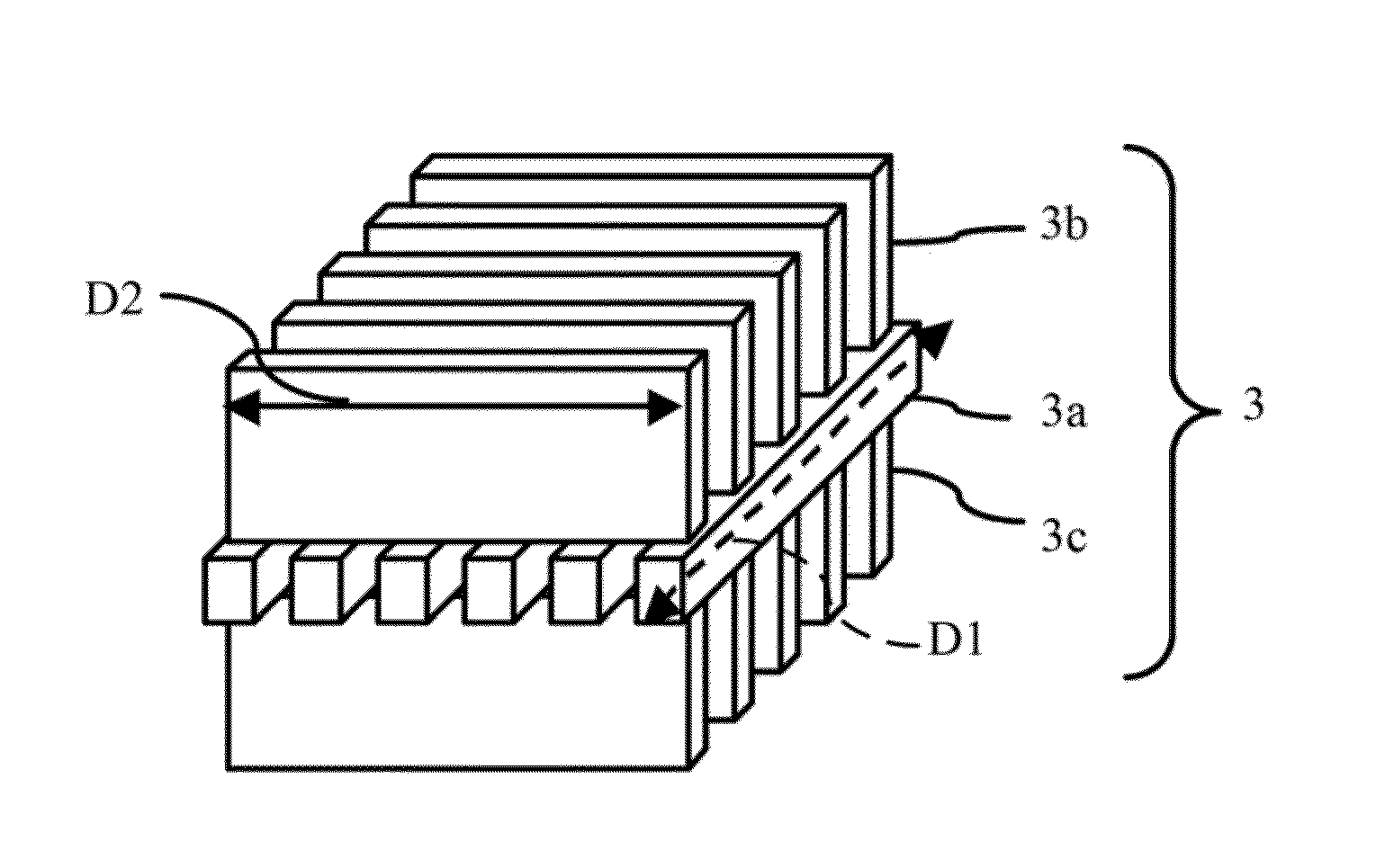
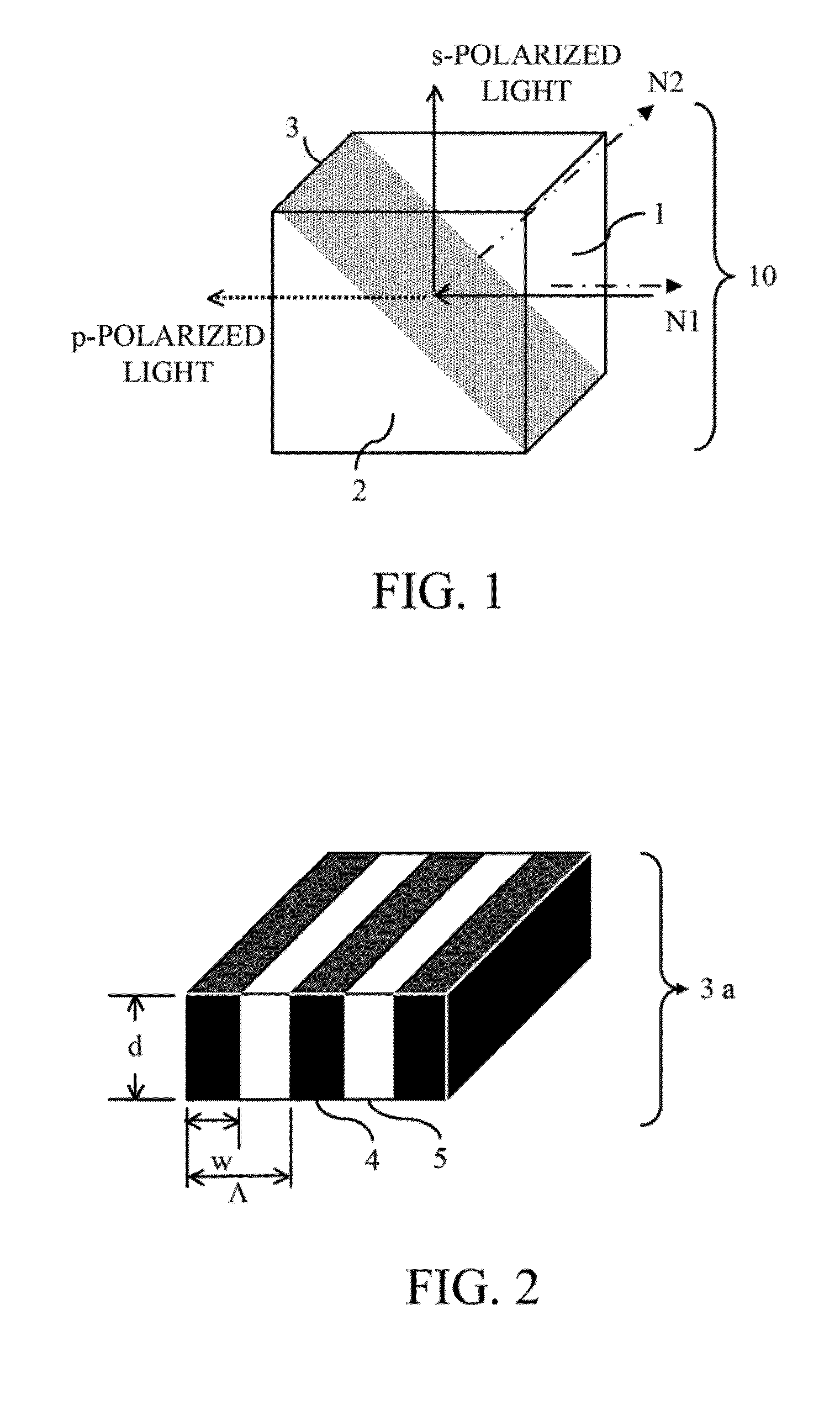
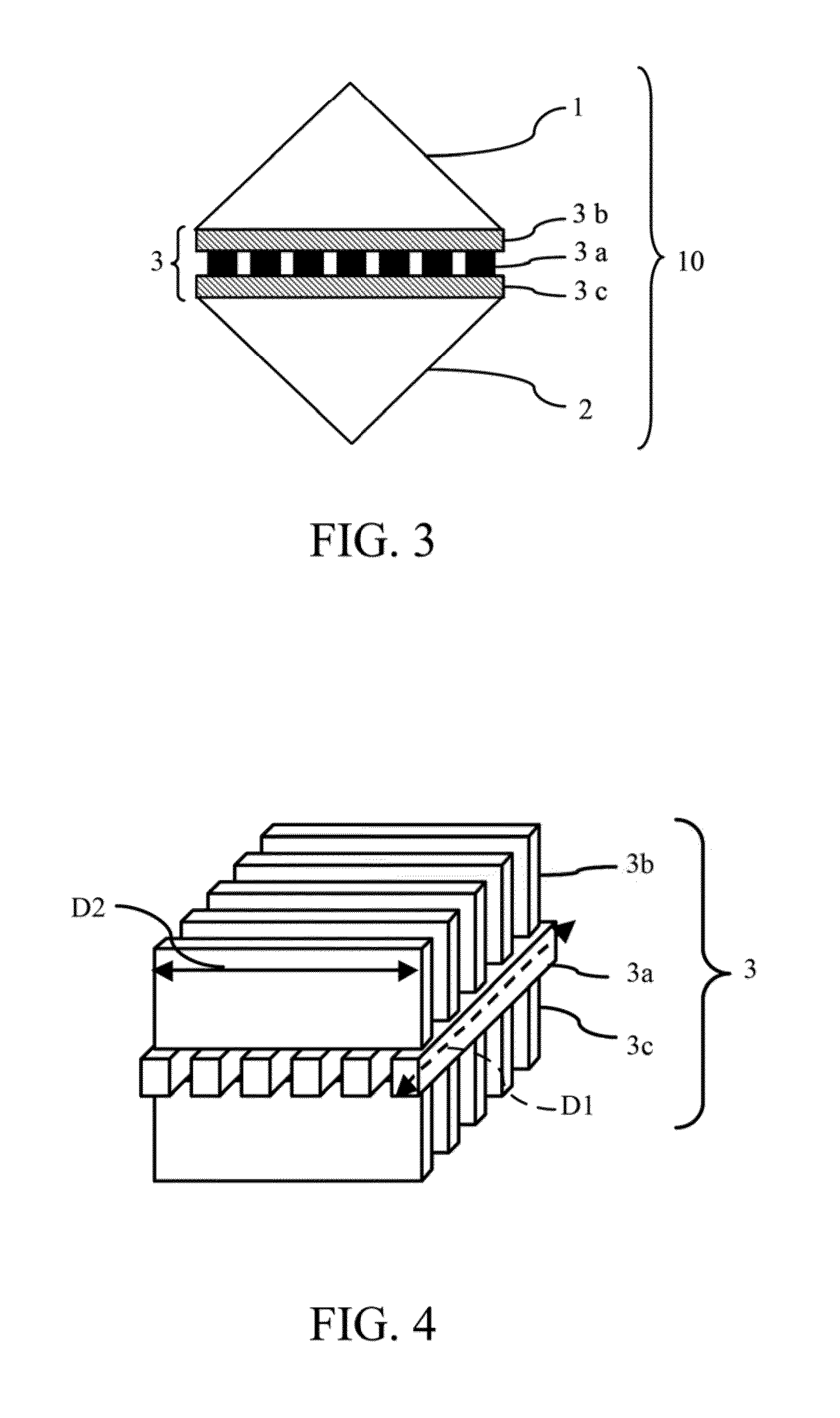
[0075]FIG. 7 shows a configuration of a polarization beam splitting element 10 that is a first embodiment (Embodiment 1) of the present invention. FIG. 8 shows a configuration of a polarization beam splitting part 3 of the polarization beam splitting element 10 of this embodiment. The polarization beam splitting element 10 of this embodiment is constituted by, in order from a beam entrance side toward a transmitted beam exit side, a prism 1, a dielectric grid 3b, a wire grid 3a and a prism 2.
[0076]The prisms 1 and 2 have a refractive index n of 1.6. The dielectric grid 3b (dielectric grating portion) is formed of a dielectric material whose refractive index n of 2.32. The wire grid 3a (metal grating portion 4) is formed of aluminum. The dielectric grid 3b has a filling factor of 0.335 and a grating thickness of 165.8 nm. The wire grid 3a has a filling factor FF of 0.55 and a grating thickness of 60 nm. The dielectric grid 3b and the wire grid 3a both have a grating per...
embodiment 2
[Embodiment 2]
[0083]Next, description will be made of a polarization beam splitting element that is a second embodiment (Embodiment 2) of the present invention. The polarization beam splitting element of Embodiment 2 is constituted by, as well as the polarization beam splitting element of Embodiment 1 shown in FIGS. 7 and 8, in order from a beam entrance side toward a transmitted beam exit side, a prism 1, a dielectric grid 3b, a wire grid 3a and a prism 2.
[0084]The prisms 1 and 2 have a same refractive index as that of Embodiment 1, and the dielectric grid 3b has same refractive index, filling factor and grating thickness as those of Embodiment 1. However, the dielectric grid 3b and the wire grid 3a both have a grating period Λ of 120 nm, and the wire grid 3a has a filling factor FF of 0.54 and a grating thickness of 70 nm.
[0085]FIGS. 11A and 11B respectively show reflectance and transmittance of the polarization beam splitting part 3 for beams having various wavelengths and perpen...
embodiment 3
[Embodiment 3]
[0093]FIG. 12 shows a configuration of a polarization beam splitting element 10 that is a third embodiment (Embodiment 3) of the present invention. FIG. 13 shows a configuration of a polarization beam splitting part 3 of the polarization beam splitting element 10 of this embodiment. The polarization beam splitting element 10 of this embodiment is constituted by, in order from a beam entrance side toward a transmitted beam exit side, a prism 1, a dielectric grid 3b, a wire grid 3a, a dielectric grid 3c and a prism 2. The dielectric grids 3b and 3c have a mutually same structure.
[0094]The prisms 1 and 2 have a refractive index n of 1.52. The dielectric grids 3b and 3c (dielectric grating portions) are formed of a dielectric material whose refractive index n of 2.32. The wire grid 3a (metal grating portion 4) is formed of aluminum. The dielectric grids 3b and 3c have a filling factor of 0.30 and a grating thickness of 169 nm. The wire grid 3a has a filling factor FF of 0....
PUM
 Abstract
Description
Claims
Application Information
 - R&D
- Intellectual Property
- Life Sciences
- Materials
- Tech Scout
- Unparalleled Data Quality
- Higher Quality Content
- 60% Fewer Hallucinations
Browse by: Latest US Patents, China's latest patents, Technical Efficacy Thesaurus, Application Domain, Technology Topic, Popular Technical Reports.
© 2025 PatSnap. All rights reserved.Legal|Privacy policy|Modern Slavery Act Transparency Statement|Sitemap|About US| Contact US: help@patsnap.com


