Sheet conveying apparatus and image forming apparatus

a conveying apparatus and a technology of forming apparatus, applied in the direction of thin material processing, roller-way, article separation, etc., can solve the problems of degrading the precision of skew feed correction, the conventional conveying apparatus described above, and insufficient skew feed correction of thin sheets. to achieve the effect of suppressing the occurrence of local deformation

Active Publication Date: 2014-08-19
CANON KK
View PDF18 Cites 9 Cited by
  • Summary
  • Abstract
  • Description
  • Claims
  • Application Information

AI Technical Summary

Benefits of technology

The present invention relates to a sheet conveying apparatus and an image forming apparatus that can correct the skew of a sheet while reducing local deformation of the sheet, which can improve the precision of the sheet feed correction.

Problems solved by technology

However, the conventional sheet conveying apparatus as described above may not perform skew feed correction sufficiently with respect to a thin sheet.
As a result, the reaction force from the abutment portion is less transmitted in the conveying direction of the sheet, and the above-mentioned curved loop to be required for correcting the skew of the sheet is hard to be formed, which degrades the precision of skew feed correction.

Method used


Image

  • Sheet conveying apparatus and image forming apparatus
  • Sheet conveying apparatus and image forming apparatus
  • Sheet conveying apparatus and image forming apparatus

Examples


first embodiment

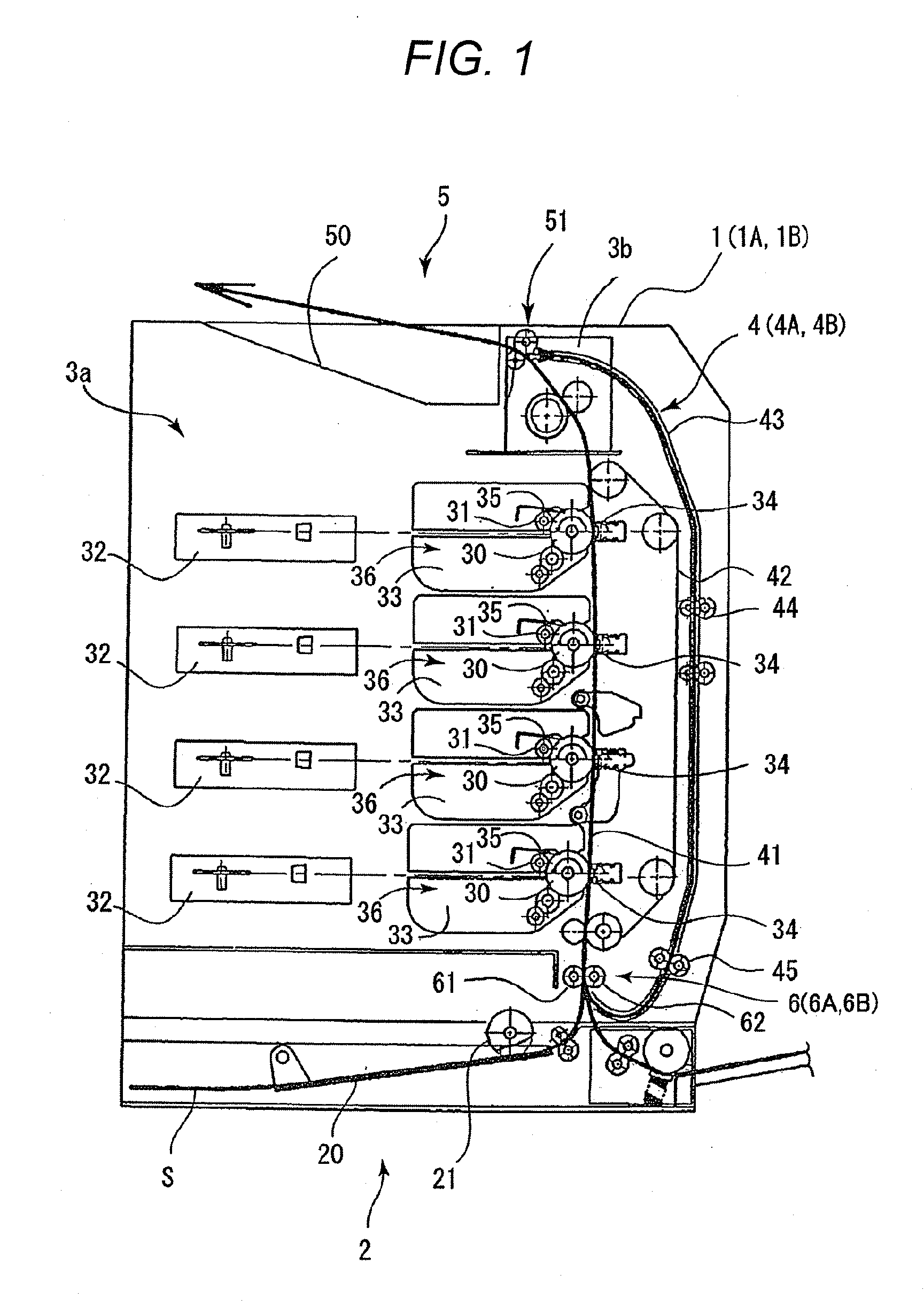
[0039]As illustrated in FIG. 1, the laser beam printer 1 includes a sheet feed portion 2 that feeds sheets S, an image forming portion 3a that forms an image, and a fixing portion 3b that fixes the image. The laser beam printer 1 further includes a sheet conveying portion 4 as a sheet conveying apparatus and a sheet discharge portion 5 that discharges the sheets S with images formed thereon.

[0040]The sheet feed portion 2 includes a feed cassette 20 in which the sheets S are contained, a feed roller 21 that feeds the sheets S contained in the feed cassette 20 to the image forming portion 3a, and a separation portion (not shown) that separates the sheets S one by one. The sheet feed portion 2 feeds the sheets S contained in the feed cassette 20 to the image forming portion 3a by the feed roller 21 while separating the sheets S one by one in the separation portion.

[0041]The image forming portion 3a forms an image on each of the sheets S based on predetermined image information. The im...

second embodiment

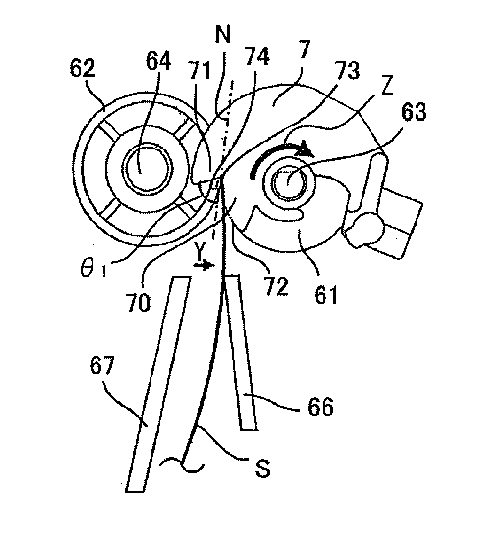
[0099]Accordingly, the local deformation at the leading edge of the sheet S, which can occur when the leading edge of the sheet S reaches the nip portion, can be suppressed, and an appropriately curved loop to be required for skew feed correction can be formed easily. Consequently, when the leading edge of the sheet S reaches the nip portion of the conveying roller pairs 61 and 62 as a result of the rotation of the shutter portion 7A, the leading edge of the sheet S does not undulate locally and can be easily corrected to the state in which the leading edge of the sheet S is positioned in a straight line in a direction orthogonal to the conveying direction. That is, the laser beam printer 1A can exhibit high skew feed correction ability.

[0100]The laser beam printer 1A according to the second embodiment includes the abutment portion 71A that is inclined so that the angle θ2 formed by the abutment surface 74A and the nip tangent N is an obtuse angle (90° or more) when the leading edg...


PUM


Abstract

A sheet conveying apparatus including: a conveying roller pair conveying a sheet by a nip portion; a shutter portion which is rotatably supported on a rotary shaft of the first conveying roller; a same radius portion, provided in the shutter portion, which is formed to have substantially the same radius as a radius of the first conveying roller; an abutment portion, provided in the shutter portion, and against which the leading edge of the sheet is abutted; and a boundary portion, provided in a boundary of the abutment portion and the same radius portion, which guides the leading edge of the sheet to the nip portion when the shutter portion is rotated by abutting the leading edge of the sheet against the boundary portion.

Description

BACKGROUND OF THE INVENTION[0001]1. Field of the Invention[0002]The present invention relates to a sheet conveying apparatus and an image forming apparatus including the same.[0003]2. Description of the Related Art[0004]In general, the accuracy of a recording position (hereinafter, also referred to as “recording precision”) of an image with respect to a sheet is one of the important factors from the viewpoint of keeping the quality in image formation. In order to enhance the recording precision in an image forming apparatus, when a sheet to be conveyed is skewed, it is necessary to correct the skewed sheet. Therefore, in conventional image forming apparatus, there have been proposed various sheet conveying apparatus having a skew feed correction function so as to enhance the recording precision.[0005]In the sheet conveying apparatus disclosed in Japanese Patent Application Laid-Open No. H09-183539, a plurality of conveying roller pairs are provided in a sheet width direction orthogo...

Claims


Application Information

Patent Timeline
Patent Type & Authority Patents(United States)
IPC IPC(8): B65H9/04
CPCB65G13/02B65H5/062B65H5/26B65H9/004B65H9/06B65H9/14
Inventor OSADA, TAKEHITOKAWANISHI, MINORUWATANABE, KENJIFURUSAWA, MOTOHIRO
Owner CANON KK
Why Eureka
Try Eureka