
Method and device for the dynamic monitoring of a lambda probe

a technology of dynamic monitoring and lambda probe, which is applied in the direction of electrical control, process and machine control, instruments, etc., can solve the problems of delay in the reaction of output signal to lambda changes, impairment of dynamics, and change in the mean lambda valu

Active Publication Date: 2014-08-05
ROBERT BOSCH GMBH
View PDF6 Cites 0 Cited by
  • Summary
  • Abstract
  • Description
  • Claims
  • Application Information

AI Technical Summary

Benefits of technology

[0007]It is therefore an object of the invention to provide a method which can detect an asymmetrical delay of the reaction of the output signal of a lambda probe.
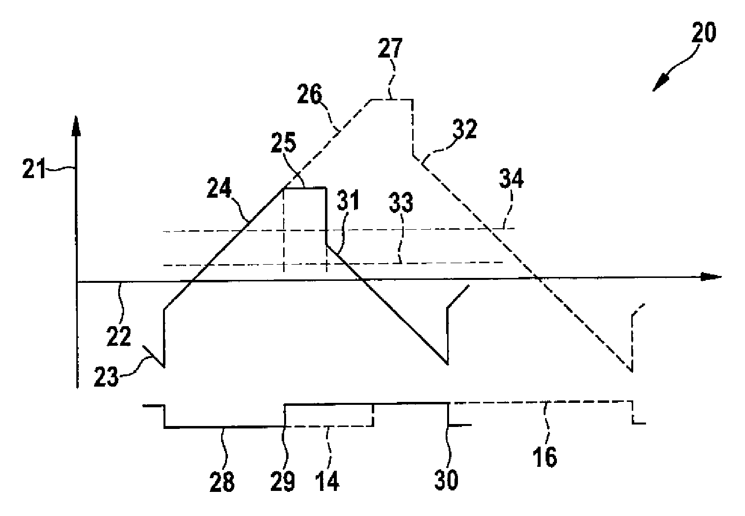
[0011]In a particularly advantageous embodiment, the characteristic signal is determined from the lambda regulating signal by virtue of the lambda regulating signal being limited to in each case a predefinable minimum value and maximum value and being filtered with a time constant of between 5 seconds and 50 seconds, preferably with a time constant of 10 seconds. This permits a particularly fast settling time of the characteristic signal, and therefore a fast detection of an asymmetrical delay of the first lambda probe.
[0012]An undesirably early response of the detection of an asymmetrical delay may be avoided by virtue of an inadmissible asymmetrical delay of the first lambda probe being inferred if, beyond a predefined time span, both the lengthening of the period exceeds the first threshold value and also the characteristic signal deviates from the second threshold value outside predetermined limits.
[0013]The object of the invention relating to the method for detecting a leak upstream of the second lambda probe is achieved in that, from the lambda regulating signal, a leakage signal is determined by virtue of the lambda regulating signal being limited to in each case a predefinable minimum value and maximum value and being filtered with a time constant of between 5 seconds and 50 seconds, preferably with a time constant of 10 seconds, and in that a leak is inferred if, in a load-speed range with high pulsation of the lambda value, the leakage signal lies further in the lean direction than a predefinable threshold value. In the event of a leak, oxygen enters from the ambient air, which oxygen is compensated by the lambda regulation based on the output signal of the second lambda probe. A leak has the effect that, in a selected load-speed range with high pulsation, for example around zero load at 2000 revolutions per minute, the leak signal is higher to an inadmissible extent than the steady-state value of the rest of the operating characteristic map. Since a leak acts only in the “lean” direction, it is necessary to monitor only a threshold in the “rich” direction.

Problems solved by technology

If a lambda probe ages, this can lead to a delayed reaction of the output signal to lambda changes, a so-called impairment of dynamics.
If the delay of the reaction of the lambda probe is asymmetrical with regard to rich-lean and lean-rich lambda changes, this can lead to a change in the mean lambda value controlled by the engine controller, as a result of which the purification action of the catalytic converters is particularly disadvantageously reduced.
As a result, an undesirably rich mixture is supplied to the internal combustion engine.

Method used


Image

  • Method and device for the dynamic monitoring of a lambda probe
  • Method and device for the dynamic monitoring of a lambda probe
  • Method and device for the dynamic monitoring of a lambda probe

Examples


Embodiment Construction

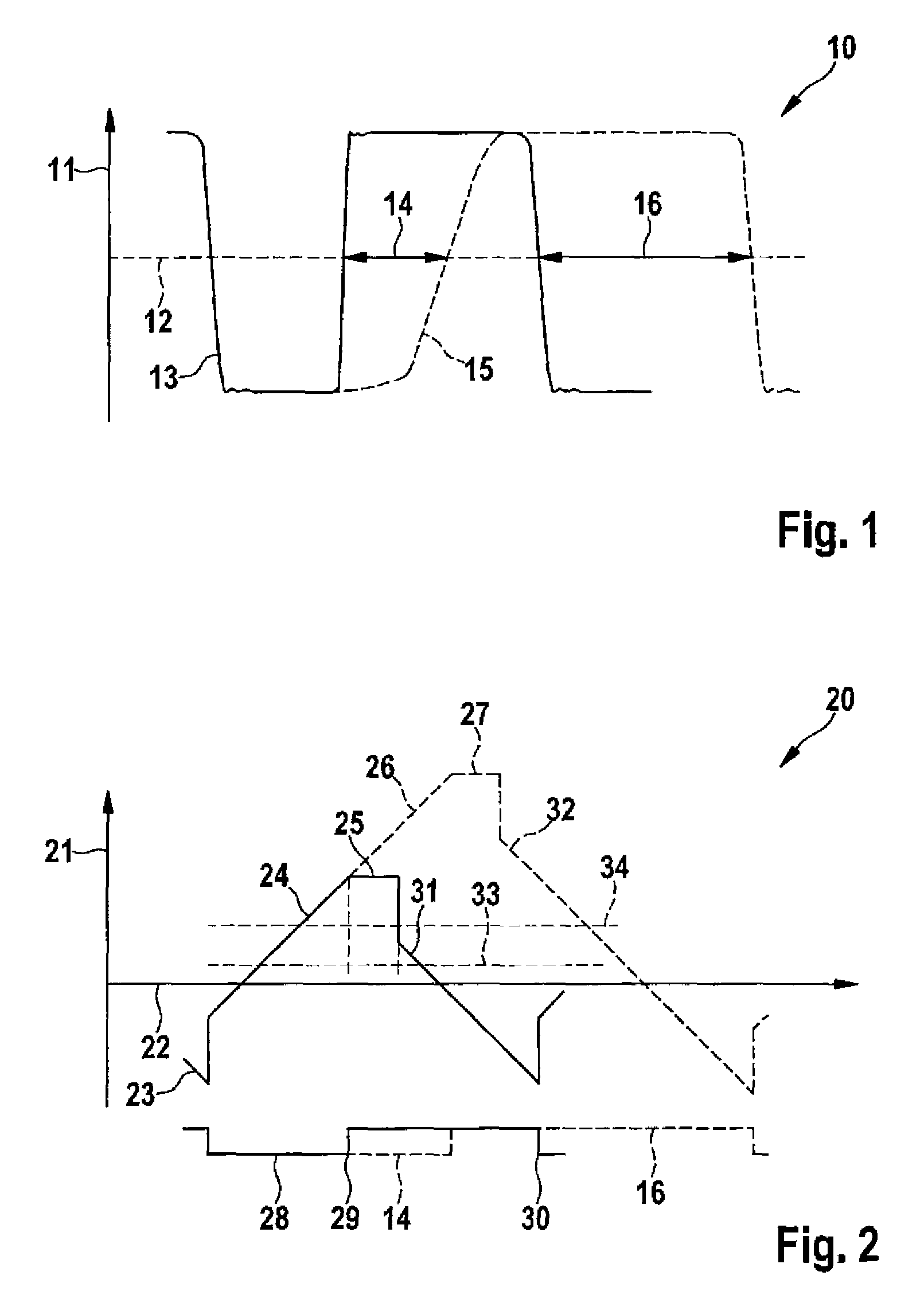
[0019]FIG. 1 shows a first lambda signal diagram 10 in which a lambda signal 13 of a first lambda probe arranged in an exhaust-gas duct of an internal combustion engine upstream of an exhaust-gas purification system is shown along a first signal axis 11 and a first time axis 12. If such a lambda probe ages asymmetrically, such that the output signal of the lambda probe reacts with a delay in the case of a lambda value varying in the “lean” direction, a delayed lambda signal 15 is generated which is delayed in relation to the lambda signal 13 by a probe delay 14. In this asymmetrically delayed lambda signal 15, voltage increases are slower than increases of the lambda signal 13, whereas the voltage decreases take place at the same speed. The period of the delayed lambda signal 15 is longer than the period of the lambda signal 13 by a period lengthening 16.

[0020]FIG. 2 shows a regulation signal diagram 20 of a signal profile of a two-position regulator based on the output signal of th...


PUM


Abstract

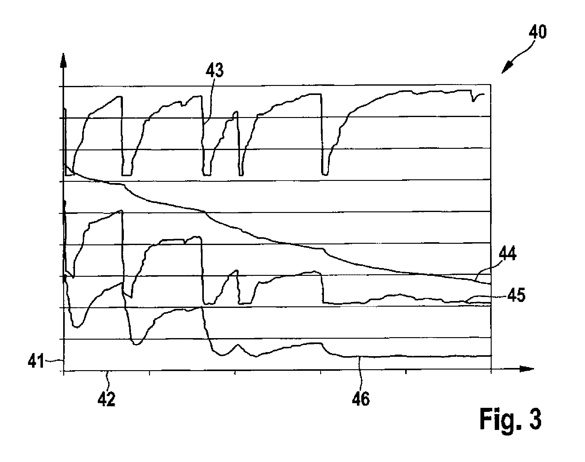
A method for the dynamic monitoring of a first lambda probe arranged in an exhaust-gas duct of an internal combustion engine upstream of an exhaust-gas purification system. A period of an output signal of the first lambda probe is determined in a controller of the internal combustion engine, and a lambda regulating signal is determined from an output signal of a second lambda probe connected downstream of the exhaust-gas purification system. A first threshold value for a lengthening of the period of the output signal of the first lambda probe is predefined, in that a characteristic signal (46) is derived from the lambda regulating signal, in that a second threshold value for an inadmissible deviation of the characteristic signal (46) is predefined, and in that an inadmissible asymmetric delay of the first lambda probe is inferred if the lengthening of the period exceeds the first threshold value and the characteristic signal (46) deviates from the second threshold value outside predetermined limits.

Description

BACKGROUND OF THE INVENTION[0001]The invention relates to a method for the dynamic monitoring of a first lambda probe arranged in an exhaust-gas duct of an internal combustion engine upstream of an exhaust-gas purification system, a period of an output signal of the first lambda probe being determined in a controller of the internal combustion engine, and a lambda correction being determined from an output signal of a second lambda probe connected downstream of the exhaust-gas purification system.[0002]The invention also relates to a method for detecting a defect upstream of a second lambda probe arranged in an exhaust-gas duct of an internal combustion engine and connected downstream of an exhaust system, a lambda correction being determined in a controller of the internal combustion engine from an output signal of the second lambda probe.[0003]The invention also relates to a device for the dynamic monitoring of a first lambda probe arranged in an exhaust-gas duct of an internal co...

Claims


Application Information

Patent Timeline
Patent Type & Authority Patents(United States)
IPC IPC(8): F02D41/00
CPCF02D41/1495F01N2560/025F02D41/1441F02D41/1454F02D41/1474
Inventor WEHMEIER, KERSTENPFEIL, MICHAELCHU, SIYUNCLEMENT, ALBRECHT
Owner ROBERT BOSCH GMBH
Learn More