Antenna device and communication terminal apparatus

a technology of communication terminal and antenna device, which is applied in the direction of solid-state devices, elongated active elements, resonance antennas, etc., can solve the problems of difficult to obtain a high gain in a state in which the casing is closed, and achieve the effect of increasing the effective antenna area of the frame-shaped radiating element, reducing or preventing capacitive coupling, and increasing gain

Active Publication Date: 2014-08-05
MURATA MFG CO LTD
View PDF696 Cites 1 Cited by
  • Summary
  • Abstract
  • Description
  • Claims
  • Application Information

AI Technical Summary

Benefits of technology

[0011]In the antenna device, a dipole antenna is provided for the feeding unit such that the plate-shaped radiating element functions as a first radiating element and the frame-shaped radiating element functions as a second radiating element. Hence, the effective antenna area of the frame-shaped radiating element is increased while reducing or preventing capacitive coupling between the plate-shaped radiating element and the frame-shaped radiating element, such that the gain is increased.

Problems solved by technology

Further, in a folding-type or slide-type mobile communication terminal apparatus there is a problem in that the impedances of ground plates and an impedance matching circuit vary in accordance with the positional relationship between the main body casing and the cover casing (for example, a state in which the cover is closed or a state in which the cover is open in a folding-type apparatus) and it is difficult to obtain a high gain in a state in which the casing is closed.

Method used


Image

  • Antenna device and communication terminal apparatus
  • Antenna device and communication terminal apparatus
  • Antenna device and communication terminal apparatus

Examples


first preferred embodiment

[0038]A mobile communication terminal apparatus 1A, which preferably is a terminal for 1 Seg (Japanese terrestrial digital TV broadcasting for mobile apparatuses) reception (470 MHz to 770 MHz), for example, includes an antenna device including a plate-shaped radiating element 21 which is arranged on a printed wiring board 20 provided inside a first casing 2 and which functions as a ground electrode, a frame-shaped radiating element 11 arranged along the inner surface of the first casing 2 to surround the plate-shaped radiating element 21, and a feeding unit 25 connected between the plate-shaped radiating element 21 and the frame-shaped radiating element 11, as illustrated in FIGS. 1A and 1B and FIGS. 2A and 2B. The feeding unit 25 includes a feeding circuit 30 that processes a wireless signal and a frequency stabilizing circuit 35 described in detail later. The plate-shaped radiating element 21 and the frame-shaped radiating element 11 are connected to the feeding circuit 30 throug...

second preferred embodiment

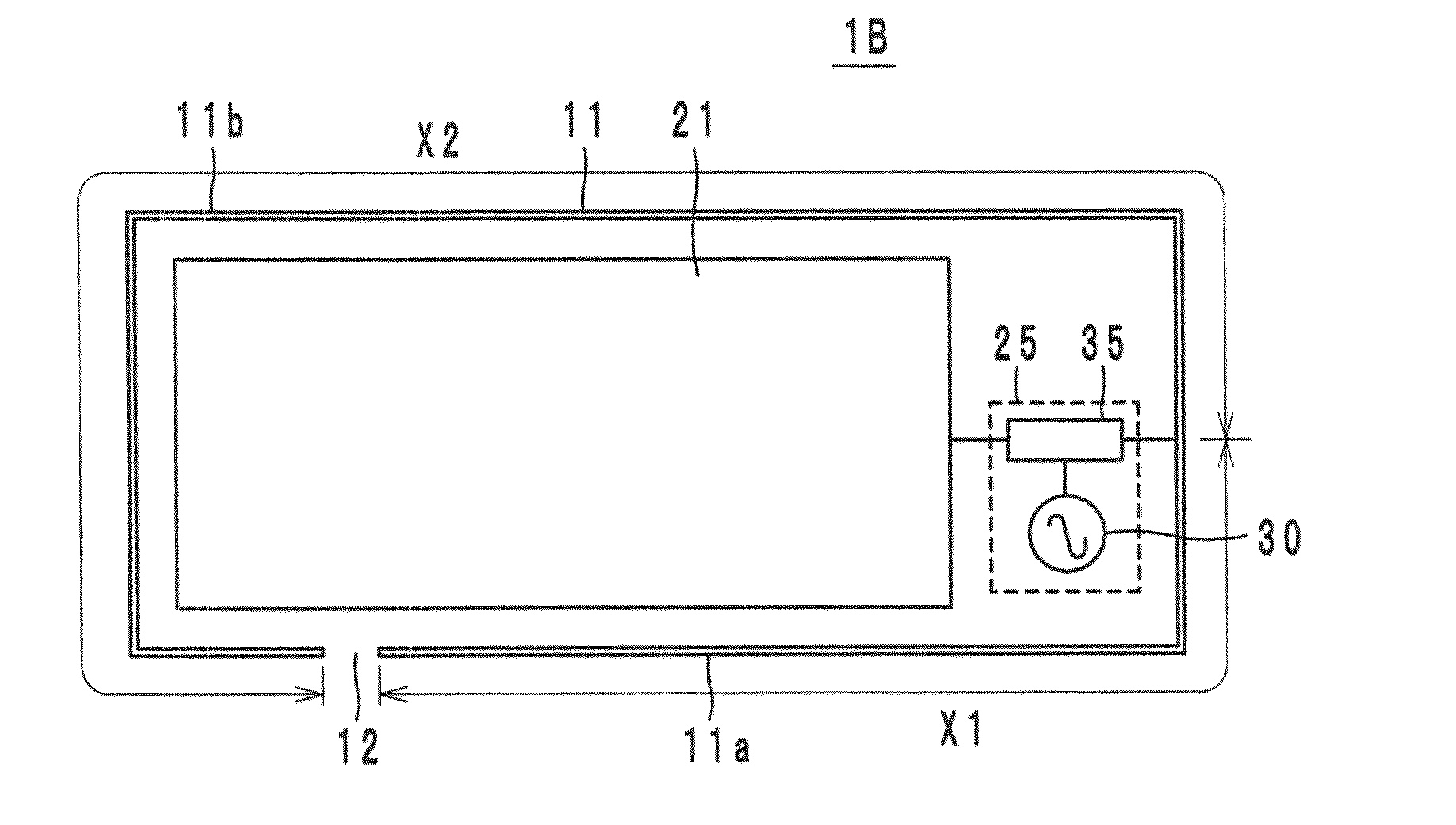
[0043]Referring to FIG. 4B, a mobile communication terminal apparatus 1B has a configuration in which a portion of a frame-shaped radiating element 11 is cut out as a gap 12. The rest of the configuration is similar to that of the first preferred embodiment described above. A potential difference is generated between the opposing end portions across the gap 12, such that the strength of an electric field at the opposing end portions is increased. Hence, the directivity of the antenna can be controlled by adjusting the position of the gap 12. Further, by dividing the frame-shaped radiating element 11 into a radiating portion 11a having a relatively short line length of X1 and a radiating portion 11b having a relatively long line length of X2, the radiating portion 11a can be made to correspond to a high-band side frequency band and the radiating portions 11a and 11b (line length of X1+X2) can be made to correspond to a low-band side frequency band in accordance with the frequency ban...

third preferred embodiment

[0044]Referring to FIG. 5, a mobile communication terminal apparatus 1C has a configuration in which a frame-shaped radiating element 11 is arranged to surround the top edge portion of the external surface of a first casing 2 as indicated by shading. The rest of the configuration and also the operations and effects of the third preferred embodiment are similar to those of the first preferred embodiment.


PUM


Abstract

An antenna device includes a plate-shaped radiating element, a frame-shaped radiating element arranged to surround the plate-shaped radiating element, and a feeding unit that includes a feeding circuit and a frequency stabilizing circuit and that is connected between the plate-shaped radiating element and the frame-shaped radiating element. The plate-shaped radiating element and the frame-shaped radiating element are connected to the feeding circuit through the frequency stabilizing circuit as a result of a first terminal portion of the frequency stabilizing circuit being connected to the frame-shaped radiating element, a second terminal portion of the frequency stabilizing circuit being connected to the plate-shaped radiating element, and a third terminal portion of the frequency stabilizing circuit being connected to the feeding circuit.

Description

BACKGROUND OF THE INVENTION[0001]1. Field of the Invention[0002]The present invention relates to antenna devices, and particularly to antenna devices mounted in mobile communication terminal apparatuses, such as cellular phones, and to communication terminal apparatuses.[0003]2. Description of the Related Art[0004]Recently, as antenna devices mounted in mobile communication terminal apparatuses, casing dipole antennas have been proposed in which a metal body (for example, a ground plate of a printed wiring board) arranged within a terminal casing is used as a radiating element, as disclosed in Japanese Unexamined Patent Application Publication No. 2004-172919, Japanese Unexamined Patent Application Publication No. 2005-6096, and Japanese Unexamined Patent Application Publication No. 2008-118359. In a dipole antenna of this type, performance similar to that of a dipole antenna can be obtained by means of differential feeding for two casing ground plates (ground plate of a main body c...

Claims


Application Information

Patent Timeline
Patent Type & Authority Patents(United States)
IPC IPC(8): H01Q9/40H01Q1/24H01Q5/00H01Q1/50H01Q9/42
CPCH01Q1/50H01Q5/0058H01Q5/0051H01Q9/42H01Q9/40H01Q1/243H01Q5/371H01Q5/357H01L2924/19105H01L2224/16225
Inventor KATO, NOBORU
Owner MURATA MFG CO LTD
Why Eureka
Try Eureka