Tool for machining workpieces

Active Publication Date: 2014-08-05
KOMET GROUP GMBH
View PDF22 Cites 12 Cited by
  • Summary
  • Abstract
  • Description
  • Claims
  • Application Information

AI Technical Summary

Benefits of technology

The patent describes a tool with a unique design that allows for better performance in different situations. The tool has a working part with wear-resistant material (tungsten carbide) and a clamping part with tough material (tungsten carbide). The two materials blend together in a transition region that is important for the tool's strength. The design of the transition region is important in ensuring that the tool has the right proportion of wear-resistant and tough materials to handle various levels of stress and impact. The tool can be tailored to specific needs by adjusting the formation of the transition region.

Problems solved by technology

The manufacture of such workpieces is complex and expensive.

Method used


Image

  • Tool for machining workpieces
  • Tool for machining workpieces
  • Tool for machining workpieces

Examples


Embodiment Construction

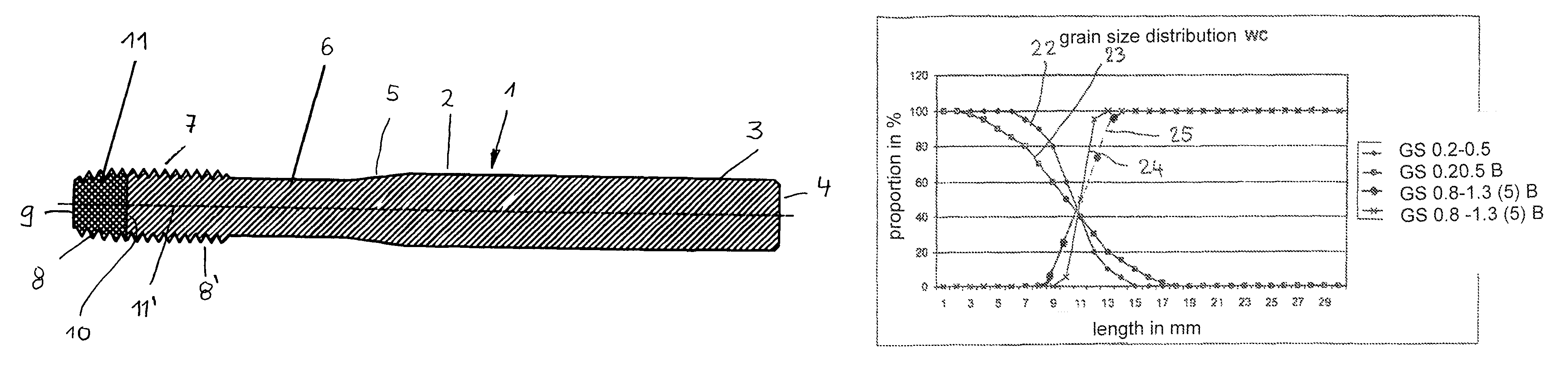
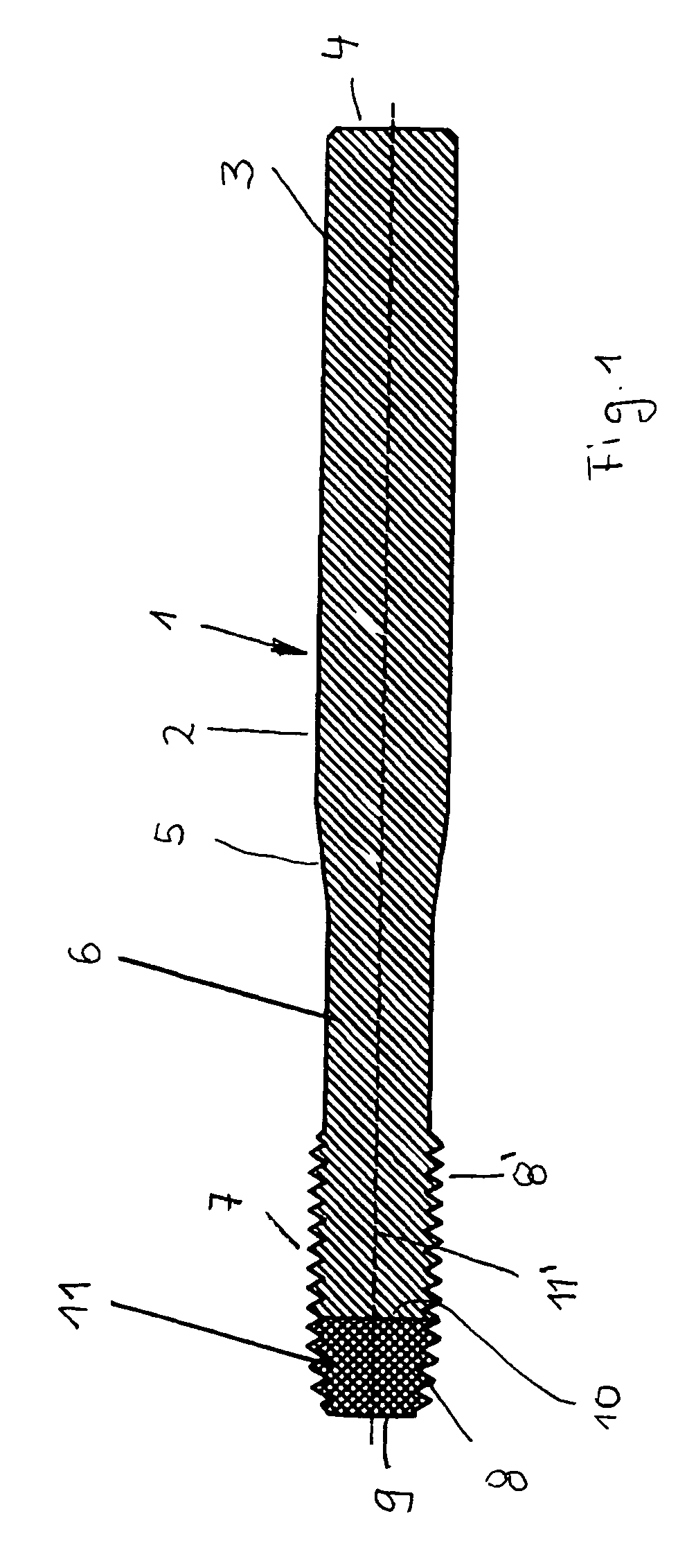
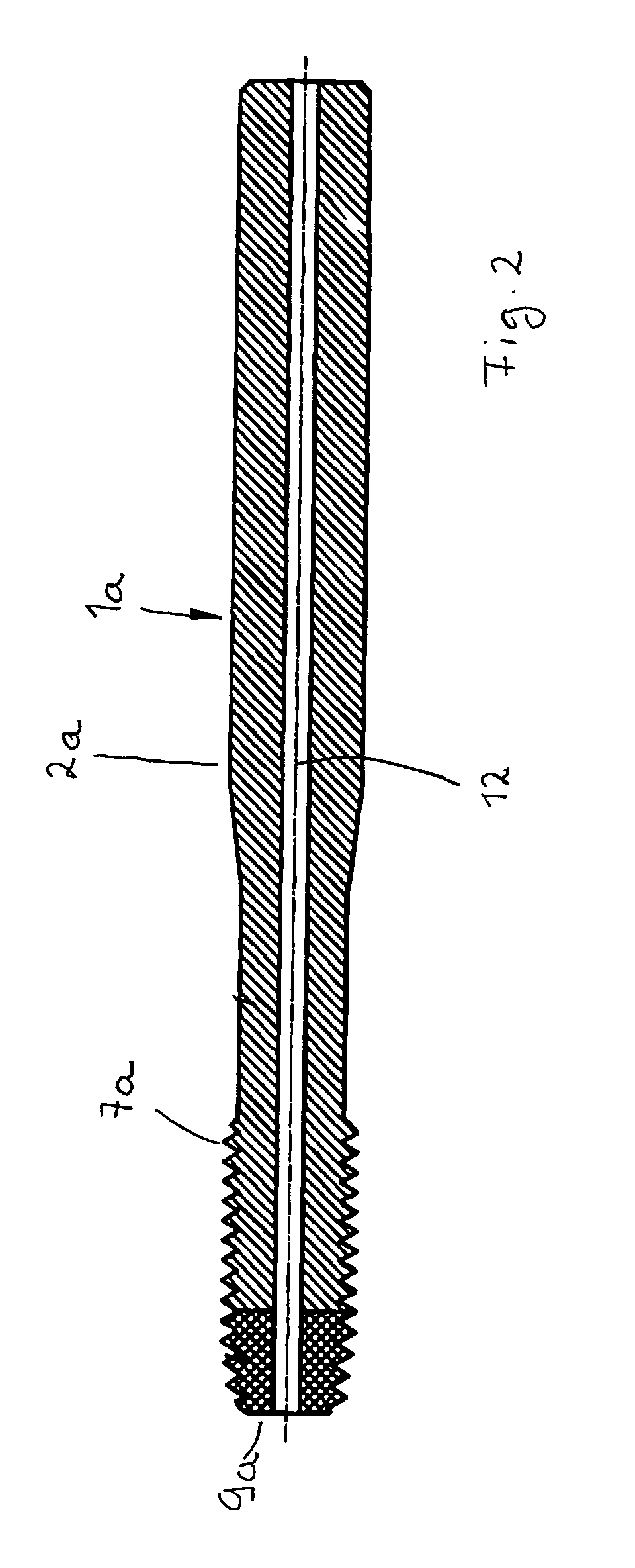
[0017]The tools illustrated in FIGS. 1 to 3 are thread formers that serve for manufacturing inner threads without cutting.

[0018]The thread former 1 according to FIG. 1 has a clamping part 2 that has a cylindrical shaft 3 with which it can be clamped in a tool receptacle. At the shaft end 4, the shaft 3 can be provided with a profiling (not illustrated) to provide an anti-rotation clamping action. The shaft 3 extends across somewhat more than half the tool length in the embodiment and passes by means of a conically tapering intermediate section 5 into a preferably cylindrical neck section 6 of the clamping part 2. The neck section 6 connects the intermediate section 5 with a working part 7. It has a first cut section 11 and a guide section 11′. The first cut section 11 has cutting edges 8 whose diameter increases in the direction of the guide section 11′ that has cutting edges 8′ with constant diameter. The end face 9 of the first cut section 11 is planar and extends perpendicularly ...


PUM

PropertyMeasurementUnit
Grain sizeaaaaaaaaaa
Fractionaaaaaaaaaa

Abstract

The tool has a clamping part (2) and a working part (11). It consists of a wear-resistant material, which contains tungsten carbide which has a grain size that lies in the range between approximately 0.2 and approximately 0.5 μm. The clamping part (2) consists of a tough material, which likewise contains tungsten carbide which has a grain size in the range between approximately 0.8 and approximately 1.3 μm. In a transitional region (11) between the working part (11) and the clamping part (2), the proportion of wear-resistant tungsten carbide decreases in the direction of the clamping part (2) to 0 and the proportion of tough tungsten carbide decreases in the direction of the working part (11) to 0. The mixing ratio between wear-resistant and tough tungsten carbide changes approximately steadily in the transitional region (10).

Description

BACKGROUND OF THE INVENTION[0001]The invention concerns a tool for machining workpieces, the tool comprising a clamping part and a working part that are comprised at least partially of a wear-resistant material and of a tough material, wherein both materials contain tungsten carbide.[0002]In known tools of this kind, the working part and a clamping part are made of the same materials, i.e., a tough core material and a hard wear-resistant outer jacket. The manufacture of such workpieces is complex and expensive. Moreover, the different materials are used also at locations where they are not even required.[0003]The invention has the object to configure such a tool in such a way that it can be configured in a simple and inexpensive way while it provides ing high wear resistance of the working part and satisfactory elasticity of the clamping part.SUMMARY OF THE INVENTION[0004]This object is solved for a tool of the aforementioned kind in accordance with the invention in that the working...

Claims


Application Information

Patent Timeline
IPC IPC(8): B23C5/16B23B51/00B23G7/02B23C5/10B23G5/18
CPCB23G7/02B23G2240/12B23B51/00B23G2225/28B23C5/10B23G5/18B23B2228/56Y10T407/19Y10T408/45Y10T408/78Y10T407/27Y10T428/12021Y10T407/14
Inventor DURST, GABRIELE
Owner KOMET GROUP GMBH
Why Eureka
Try Eureka