
Thrust reverser for a dual-flow turbine engine nacelle

a turbine engine and thrust reverser technology, applied in the direction of steering components, aircraft navigation control, air transportation, etc., can solve the problems of reducing the surface area of the inner structure which could be used for acoustic purposes, generating numerous aerodynamic perturbations, and complicating dismounting, so as to achieve easy industrial production

Inactive Publication Date: 2014-08-05
AIRCELLE
View PDF3 Cites 19 Cited by
  • Summary
  • Abstract
  • Description
  • Claims
  • Application Information

AI Technical Summary

Benefits of technology

The invention is a thrust reverser for an aircraft that overcomes the drawbacks of existing designs. It includes a sliding cowl and a blocker door that are connected to an actuating cylinder, allowing the cowl to change from a closed position to an open position. A diaphragm is used to improve sealing and a reinforced guide rail prevents bending of the actuating cylinder. The technical effects of this design include improved efficiency, easy manufacture, and reduced weight.

Problems solved by technology

Yet since the guiding links pass through the bypass duct, they generate numerous aerodynamic perturbations in the secondary air stream.
Also, the fixing of these links on the inner structure requires the installation of fixed hinge points on the latter, which reduces the surface area of the inner structure which could be used for acoustic treatment of the said inner structure.
On this account, the thrust reverser structure and the inner structure are not independent of each other, which complicates dismounting thereof when maintenance operations on the nacelle or turbojet so require, in particular with external structures of so-called > type i.e. manufactured in a single piece completely surrounding the turbojet, contrary to structures of so-called > type comprising two semi-parts joined together around the turbojet.
However, a said thrust reverser is fairly complex to manufacture on industrial scale, and despite its advantages the implementation thereof entails some difficulties.
Additionally, since the end of the link is fixed onto the driving slider, this interferes with the reversing vane, reducing flow reversing efficiency and degrading the installation in the area of interference.

Method used


Image

  • Thrust reverser for a dual-flow turbine engine nacelle
  • Thrust reverser for a dual-flow turbine engine nacelle
  • Thrust reverser for a dual-flow turbine engine nacelle

Examples


Embodiment Construction

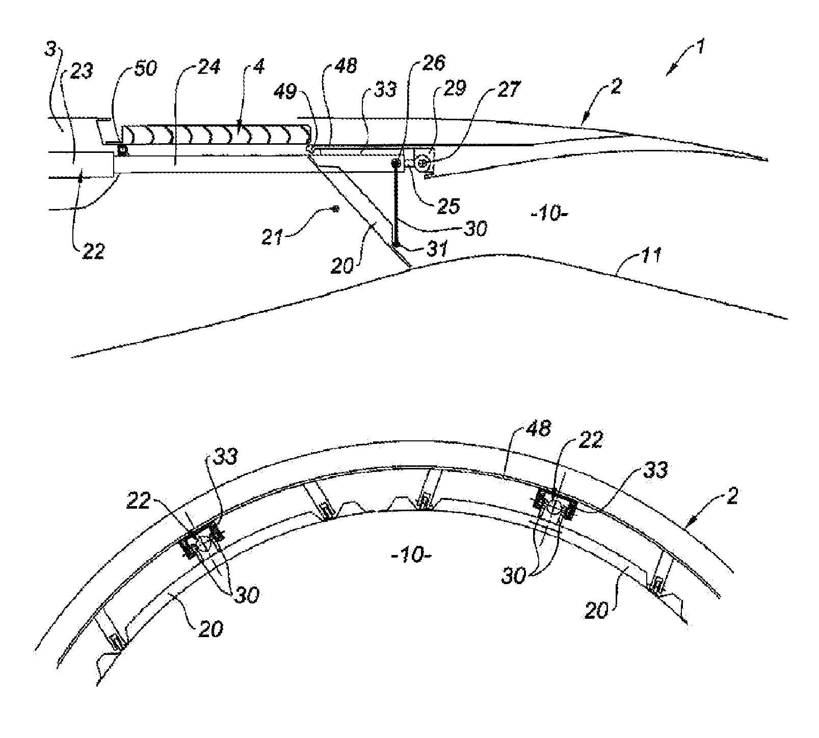
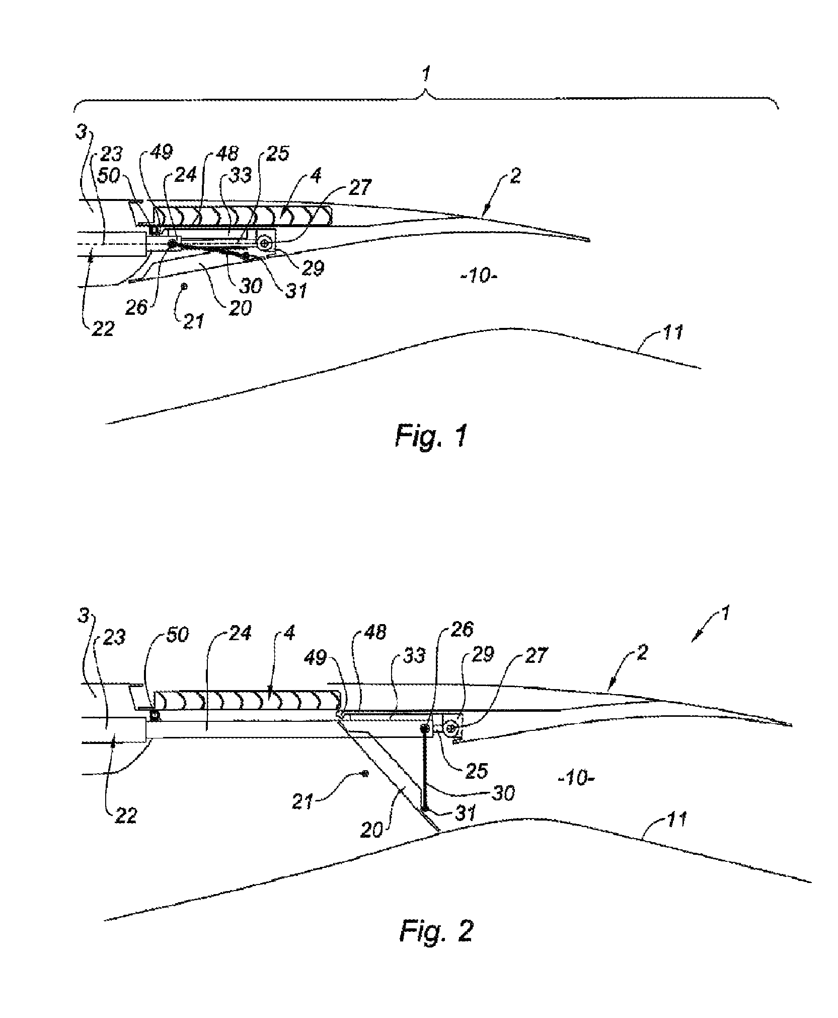
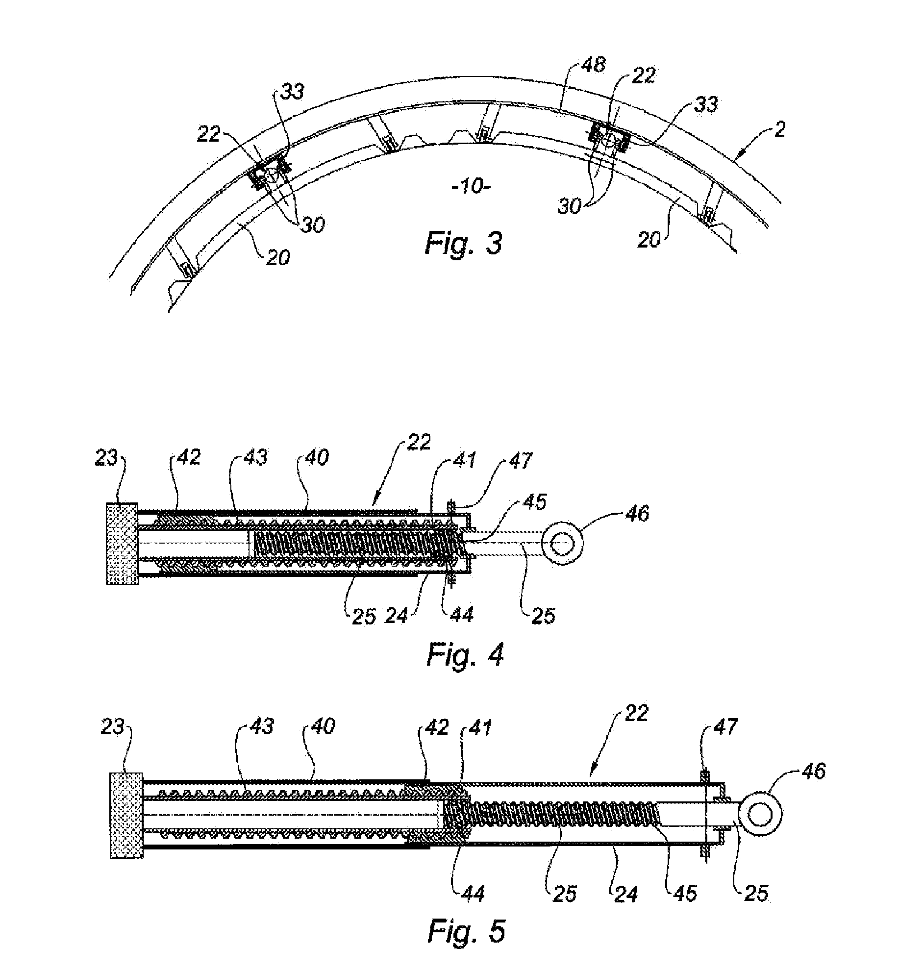
[0073]The thrust reverser 1 in FIGS. 1 to 12 is associated with a turbofan jet engine (not illustrated) and comprises an outer nacelle which, with an inner concentric structure 11, defines an annular bypass duct 10 allowing the passing of the cold air stream.

[0074]A cowl 2 sliding longitudinally is formed of two semi-cylindrical parts mounted on the nacelle so that they can slide along slide-rails (not illustrated).

[0075]An opening provided with fixed diverting means, in particular in the form of diverting vanes 4, is arranged in the outer nacelle of the thrust reverser 1. This opening, under conditions of direct thrust of the gases, is closed by a sliding cowl 2 and it is uncovered under thrust reversing conditions via a movement in longitudinal translation in downstream direction (with reference to the direction of flow of the gases) of the sliding cowl 2 along the main longitudinal centreline of the nacelle.

[0076]A plurality of blocker doors 20 distributed over the circumference ...


PUM


Abstract

The invention relates to a thrust reverser (1) for the nacelle of a dual-flow turbine engine, in which the bypass means (4) and the actuation jacks (22) of the sliding cowling (2) and of the reverse flaps (20) are arranged in two substantially parallel planes arranged above one another in the radial direction of the nacelle. The invention also relates to a nacelle for a dual-flow turbine engine that comprises such a thrust reverser.

Description

TECHNICAL FIELD[0001]The present invention concerns a so-called cascade vane thrust reverser for a jet engine.BACKGROUND[0002]An aircraft is propelled by several turbojet engines each housed in a nacelle which also houses an assembly of ancillary actuating devices related to the functioning thereof and ensuring various functions when the turbojet engine is or is not in operation. These ancillary actuating devices particularly comprise a mechanical thrust reverser system.[0003]More precisely, a nacelle generally has a tubular structure comprising an air inlet upstream of the turbojet engine, a median section intended to surround a fan of the turbojet engine, a downstream section housing the thrust reverser means and intended to surround the combustion chamber of the turbojet engine, and generally ends in an exhaust nozzle whose outlet lies downstream from the turbojet.[0004]Modern nacelles are intended to house a turbofan jet engine capable, via the rotating fan blades, of generating...

Claims


Application Information

Patent Timeline
Patent Type & Authority Patents(United States)
IPC IPC(8): F02K3/02B05B12/00B63H11/10B63H25/46F02K1/00F02K1/72F02K1/76
CPCF02K1/72F02K1/763F05D2270/66Y02T50/671Y02T50/60
Inventor VAUCHEL, GUY, BERNARD
Owner AIRCELLE
Learn More