System and method for microwave ranging to a target in presence of clutter and multi-path effects
a microwave range and clutter technology, applied in the field of electromagnetic distance measurement, can solve the problems of limited bandwidth of transmitted pulses, multipath effects, and difficulty in identifying individual targets,
- Summary
- Abstract
- Description
- Claims
- Application Information
AI Technical Summary
Benefits of technology
Problems solved by technology
Method used
Image
Examples
example 1
[0073]The following simulation illustrates the process of ranging to a tag using the process outlined above.
[0074]The radar ranging process used in this example performs a subtraction of processed signals:[0075]Transmit radar signals coordinated with the modulation state of the tag[0076]Receive reflected radar signals for each of the modulation states of the tag[0077]Use an analog to digital converter (A / D) or equivalent to sample the signals[0078]Process each of the sampled signals using a fast Fourier transform (FFT) to produce complex signal spectrums[0079]Form the complex conjugate of the FFT of the transmit signal[0080]Form products by multiplying the complex conjugate of the transmit signal with the FFT of each received signal individually[0081]Produce a correlation for each received signal individually by performing an inverse FFT of each product[0082]Subtract the correlation obtained with the tag modulation in one state from the correlation with the tag modulation in the oth...
example 2
[0089]A second example follows the process of Example 1 with several modifications. In this example, parameters and modulations are chosen to improve performance.
[0090]Example 2 uses the following parameters:[0091]A transmit chirp radar signal with constant amplitude (other than limited rise and fall times) with a frequency that increases linearly by 100 MHz in 2048 ns[0092]Rise and fall times limited to 100 ns to reduce out of band emissions[0093]Downconvert the received signals into the band from 50 MHz to 150 MHz[0094]Clutter consisting of two stationary targets, the return radar signal from the first has a round trip time delay of 60 ns and a relative strength of 1, and the return radar signal from the second has a round trip time delay of 70 ns and a relative strength of 0.3[0095]A radar return signal from a tag with a round trip time delay of 65 ns and a relative strength of 0.2 when modulating in Mode B and 0.0 when modulating in Mode A[0096]Uncorrelated white Gaussian noise ...
example 3
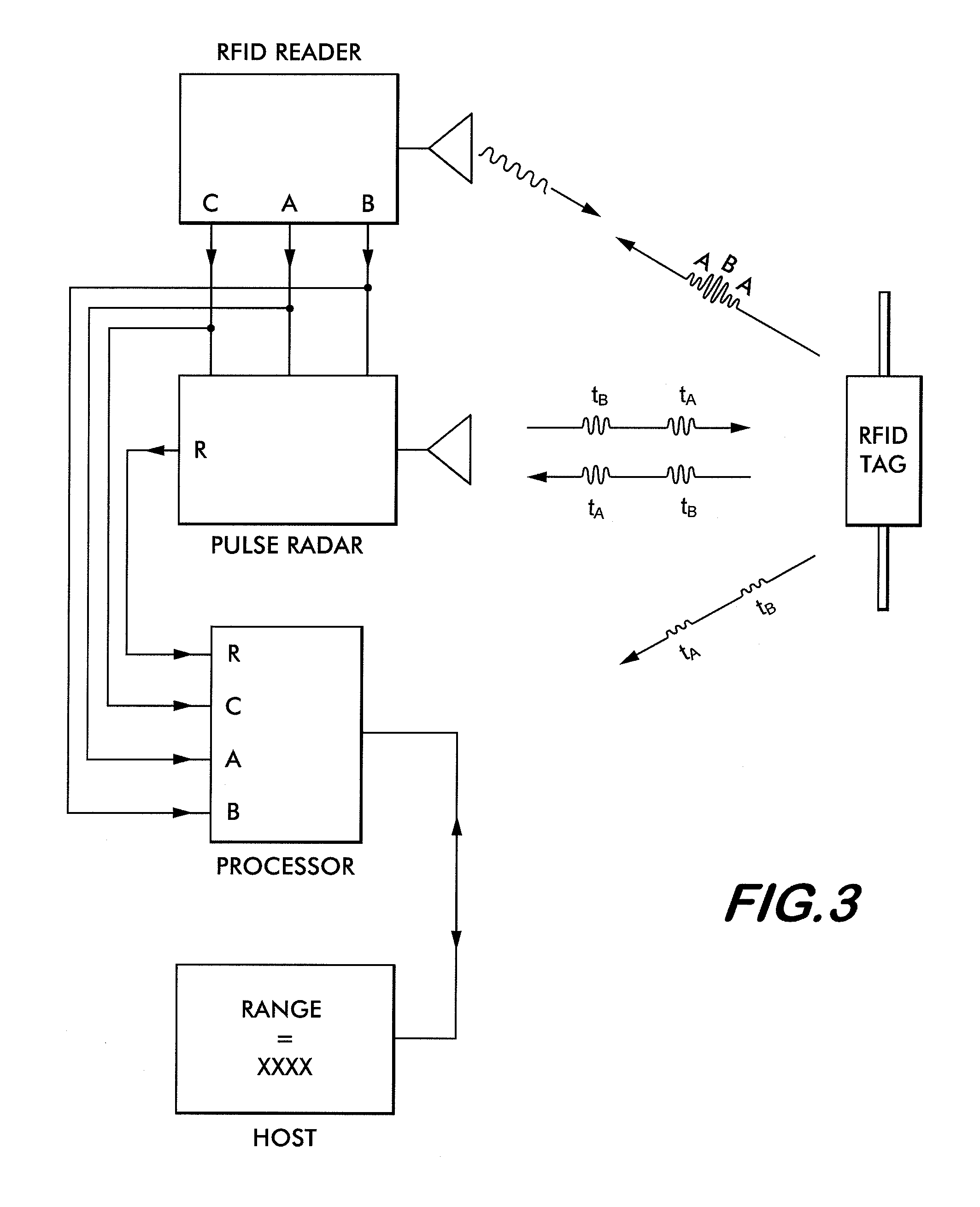
[0102]Methods shown in Example 1 and Example 2 illustrate the technique of differential pulse compression radar to measure the distance to a tag in the presence of clutter and multipath. Example 2 also shows the ability of the methods to suppress amplitude noise as shown in FIG. 6b through FIG. 6g. Implementation of the methods are improved by consistency in timing, frequency and amplitude and minimizing jitter of the transmitted radar pulses and subsequent data processing. An improved differential pulse compression radar is shown in FIG. 7. The RFID Reader, Host and data processing sections of FIG. 3 have been omitted for clarity.
[0103]Operation is performed using a minimum set of signals. First, timing is derived from a signal (from a reader or other source) indicting the modulation state of the tag being read. An example of such a signal is the “TAG MODULATION STATE” of FIG. 4 and “Modulation State from Reader” on FIG. 7. Further referring to FIG. 7, Signal Generator 1 (Agilent M...
PUM
 Abstract
Description
Claims
Application Information
 - R&D
- Intellectual Property
- Life Sciences
- Materials
- Tech Scout
- Unparalleled Data Quality
- Higher Quality Content
- 60% Fewer Hallucinations
Browse by: Latest US Patents, China's latest patents, Technical Efficacy Thesaurus, Application Domain, Technology Topic, Popular Technical Reports.
© 2025 PatSnap. All rights reserved.Legal|Privacy policy|Modern Slavery Act Transparency Statement|Sitemap|About US| Contact US: help@patsnap.com


