Steering wheel heater and steering wheel
a heater device and steering wheel technology, applied in the field of steering wheel heaters and steering wheels, can solve the problems of poor s/n ratio, reduced circuit sensitivity, poor sensitivity of detection circuits, etc., and achieve good sensitivity for contact detection, reduce or eliminate parasitic capacitance effects
- Summary
- Abstract
- Description
- Claims
- Application Information
AI Technical Summary
Benefits of technology
Problems solved by technology
Method used
Image
Examples
exemplary embodiment 1
Variation of Exemplary Embodiment 1
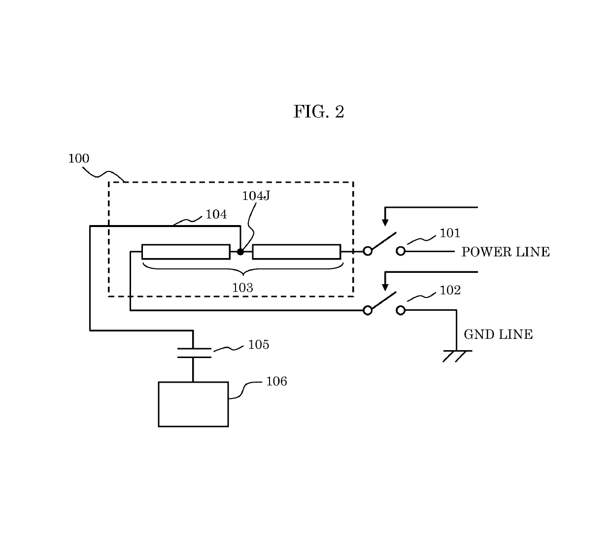
[0080]FIG. 5 is a block diagram of another configuration example of the steering wheel heater device according to exemplary embodiment 1. The configuration shown in FIG. 5 is the same as that shown in FIG. 2, except that adjusted capacitors Ca and Cb are added.
[0081]Adjusted capacitor Ca is connected in parallel to switch 101. Adjusted capacitor Cb is connected in parallel to switch 102. Adjusted capacitors Ca and Cb are capacitors whose capacitance values are semi-fixedly adjustable.
[0082]While contact detection circuit 106 is inactive (i.e., while the steering wheel heater device is heating when switches 101 and 102 are on), adjusted capacitors Ca and Cb are being shorted in response to switches 101 and 102 turning on, and thus have no effects on the heating of the steering wheel heater device. In contrast, when switches 101 and 102 are off, adjusted capacitors Ca and Cb are connected in parallel to the parasitic capacitance of switch 101 and the...
exemplary embodiment 2
Variation 2 of Exemplary Embodiment 2
[0111]FIG. 12 is a block diagram of configuration of a steering wheel heater device according to variation 2 of exemplary embodiment 2.
[0112]Variation 2 of exemplary embodiment 2 is the same as exemplary embodiment 2 shown in FIG. 10, except that inductive element 135 is disposed between GND and one end of heating wire 103.
[0113]In variation 2, a portion of the wiring pattern of heating wire 103 and inductive element 135, which is an external inductor, prevent contact detection circuit 106 and GND from being directly coupled. Inductive element 135 may be added in such a manner if the portion of the wiring pattern of heating wire 103 does not yield impedance sufficient for reducing or eliminating the effects of parasitic capacitance on capacitance between the human hand and the steering wheel.
Exemplary Embodiment 3
[0114]In exemplary embodiments 1 and 2, and variations thereof, the configurations of the steering wheel heater device have been shown,...
exemplary embodiment 3
Variation 2 of Exemplary Embodiment 3
[0124]FIG. 16 is a block diagram of configuration of a steering wheel heater device according to variation 2 of exemplary embodiment 3.
[0125]Variation 2 of exemplary embodiment 3 is the same as exemplary embodiment 3 shown in FIG. 15, except that inductive element 135 is attached to a GND line. This can compensate for the case where heater wire 103D does not yield impedance sufficient for reducing or eliminating the effects of parasitic capacitance on capacitance between a human hand and a steering wheel.
[0126]While contact detection circuits 106, S1, and S2 are connected to lead-out wire 104 via coupling capacitor 105 in the exemplary embodiments and variations thereof described above, a diode may be employed in place of coupling capacitor 105. In this case the diode has an anode connected to contact detection circuits 106, S1, and S2, and a cathode connected to lead-out wire 104. Alternatively, coupling capacitor 105 may be eliminated and conta...
PUM
 Abstract
Description
Claims
Application Information
 - R&D
- Intellectual Property
- Life Sciences
- Materials
- Tech Scout
- Unparalleled Data Quality
- Higher Quality Content
- 60% Fewer Hallucinations
Browse by: Latest US Patents, China's latest patents, Technical Efficacy Thesaurus, Application Domain, Technology Topic, Popular Technical Reports.
© 2025 PatSnap. All rights reserved.Legal|Privacy policy|Modern Slavery Act Transparency Statement|Sitemap|About US| Contact US: help@patsnap.com


