
Voiced interval command interpretation

a voice and interval technology, applied in the field of voice activation technology, can solve the problems of inability to achieve economic development, inability to support single-purpose devices, and inability to achieve full speech recognition, etc., and achieve the effects of high sensitivity, fast recording, and increased gain

Inactive Publication Date: 2014-07-15
ELOQUI VOICE SYST LLC
View PDF20 Cites 5 Cited by
  • Summary
  • Abstract
  • Description
  • Claims
  • Application Information

AI Technical Summary

Benefits of technology

The invention is a way to understand what people are saying by detecting specific sounds and intervals between them. This method is effective, economical, and very fast. It can be implemented using a low-cost microcontroller and is versatile enough to control data acquisition devices using voice commands.

Problems solved by technology

Unfortunately, the current art in speech recognition offers little support for single-purpose devices.
Currently such devices have no economic path to commercialization because full speech recognition is far too expensive and cumbersome.
Many voice-activated systems require a link to remote supercomputers, further increasing the cost and complexity.
Another problem with current voice-activation technology is its slow response time.
Current speech recognition routines cannot provide a quick trigger because of the time needed to perform the speech recognition.
Another big problem is command interpretation error.
Prior systems are notoriously error-prone.
Even after a tedious “training” process, current speech recognition systems routinely misinterpret commands, or miss them completely, for no apparent reason.
Moreover, speech recognition systems are necessarily speaker-dependent and are susceptible to complex backgrounds such as those often found in office and laboratory environments.
Such a technology would enable voice-activated counting, interval timing, pulse generation, voltage measurement, size and distance measurement, weighing, and a host of other test and control devices that are not economically or technically feasible with current technology.

Method used


Image

  • Voiced interval command interpretation
  • Voiced interval command interpretation
  • Voiced interval command interpretation

Examples


Embodiment Construction

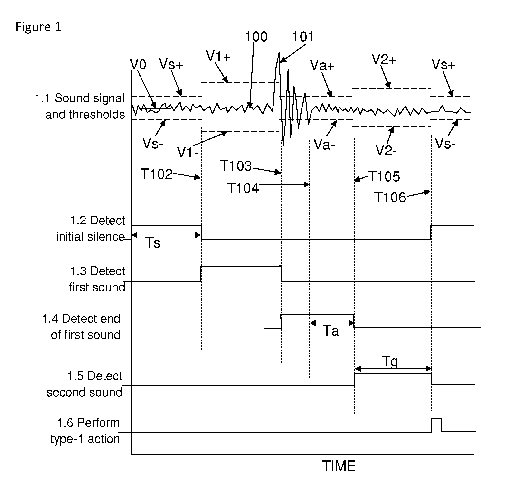
[0050]FIG. 1 shows a series of graphs or traces, similar to oscilloscope traces, showing how the inventive method is used to interpret a type-1 command. The first trace in FIG. 1, labeled “1.1 Sound signal and thresholds”, shows the amplified and filtered analog sound signal 100, with voltage on the vertical axis and time on the horizontal axis. The sound signal 100 is bipolar, not rectified, and thus exhibits both positive and negative excursions relative to the mean signal during silence. The voiced interval 101 of a type-1 command can be seen on the sound signal 100, as well as continuous low-amplitude variations due to electronic noise. Various threshold values are also shown as dashed horizontal lines. A solid horizontal line labeled V0 indicates the mean silent signal. Certain times are also indicated by vertical dotted lines.

[0051]The second trace in FIG. 1, labeled “1.2 Detect initial silence”, shows a time period of length Ts which is demarked to determine that all prior so...


PUM


Abstract

A method is disclosed for controlling a voice-activated device by interpreting a spoken command as a series of voiced and non-voiced intervals. A responsive action is then performed according to the number of voiced intervals in the command. The method is well-suited to applications having a small number of specific voice-activated response functions. Applications using the inventive method offer numerous advantages over traditional speech recognition systems including speaker universality, language independence, no training or calibration needed, implementation with simple microcontrollers, and extremely low cost. For time-critical applications such as pulsers and measurement devices, where fast reaction is crucial to catch a transient event, the method provides near-instantaneous command response, yet versatile voice control.

Description

BACKGROUND OF THE INVENTION[0001]The invention relates to voice-activation technology, and particularly to means for interpreting spoken commands by demarking time intervals with and without voiced sound.[0002]Voice-activation is an exciting, emerging technology. Unfortunately, the current art in speech recognition offers little support for single-purpose devices. A wide range of potential applications, particularly in test and measurement instrumentation, require only two or three specific operations under voice control. Currently such devices have no economic path to commercialization because full speech recognition is far too expensive and cumbersome. Many voice-activated systems require a link to remote supercomputers, further increasing the cost and complexity.[0003]Another problem with current voice-activation technology is its slow response time. Many special-purpose applications require a very fast response, especially when the response triggers a measurement. For example, a...

Claims


Application Information

Patent Timeline
Patent Type & Authority Patents(United States)
IPC IPC(8): G10L15/06G10L15/20G10L15/26G10L19/00G10L19/12G10L21/00G10L21/02
CPCG10L25/51G10L25/93
Inventor NEWMAN, DAVID, EDWARD
Owner ELOQUI VOICE SYST LLC
Learn More