Display method and display device
a display device and liquid crystal technology, applied in the field of display devices, can solve the problems of inability to achieve desired display gray scale, a certain amount of time before the alignment condition of the liquid crystal layer, and the response speed of the liquid crystal display device is generally very inferior to other display devices such as crt in terms of display signal response speed, etc., to achieve the effect of reducing the response time of the pixel, reducing the blurring of moving images, and increasing the brightness of the pixel
- Summary
- Abstract
- Description
- Claims
- Application Information
AI Technical Summary
Benefits of technology
Problems solved by technology
Method used
Image

Examples
first embodiment
Arrangement of Display Device
[0086]With reference to FIGS. 2 through 9, the following describes one example of a liquid crystal display device (hereinafter abbreviated to LCD) to which the display device of the present invention is applied.
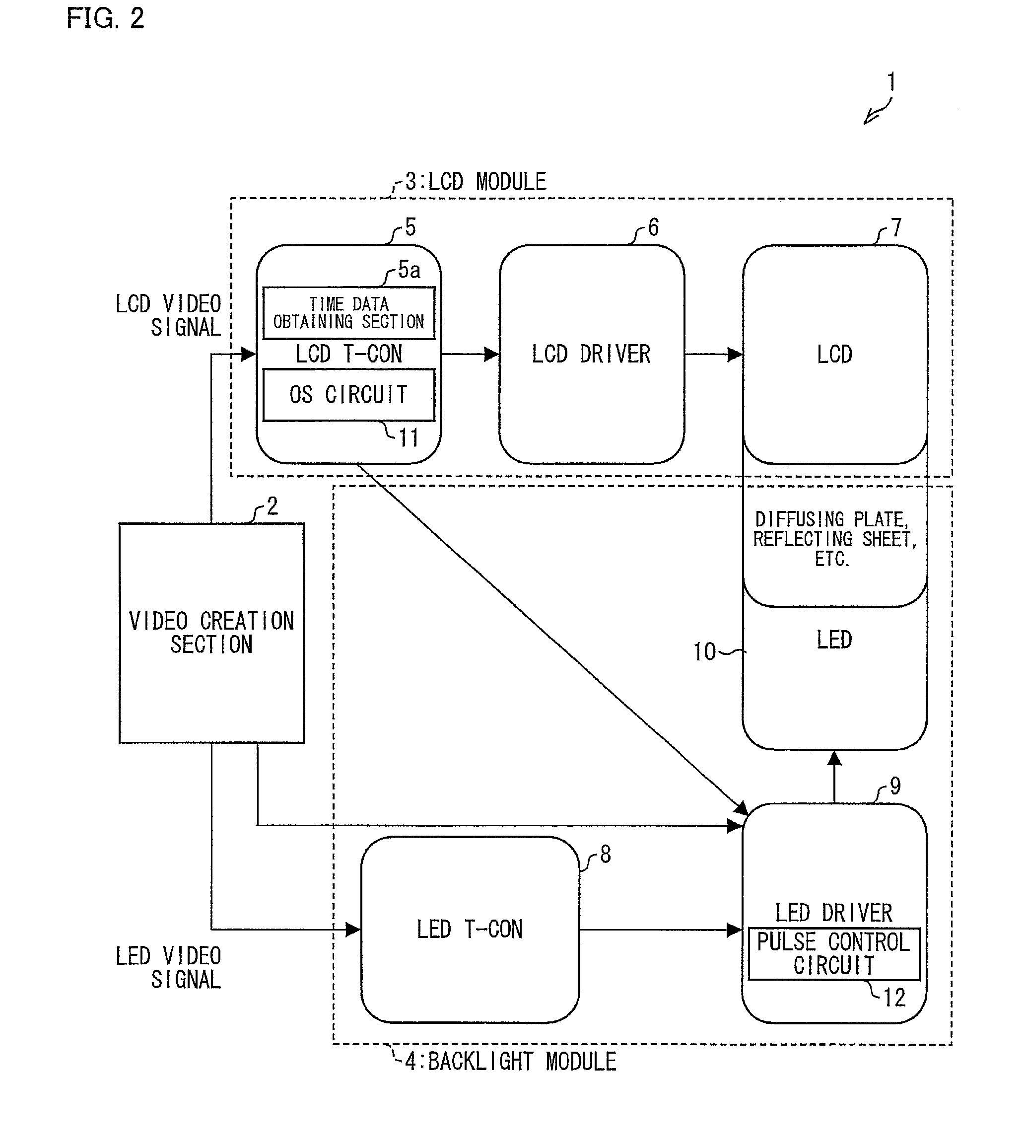
[0087]FIG. 2 is a view schematically showing an internal arrangement of an LCD 1. In the LCD 1, a light emitting diode (hereinafter abbreviated to LED) 10 is used as a light source. Instead of the LED 10, another light emitting element such as an organic electroluminescence (EL) element, an inorganic EL element, or the like, may be used as the light source of the LCD 1.
[0088]As shown in FIG. 2, the LCD 1 includes, a video creation section 2, an LCD module 3, and a backlight module 4. The LCD module 3 includes an LCD timing control circuit (hereinafter referred to as LCD_T-CON) 5, an LCD driver 6, and an LCD panel 7. The backlight module 4 includes an LED timing control circuit (hereinafter referred to as LED_T-CON) 8, an LED driver 9, and a plural...
second embodiment
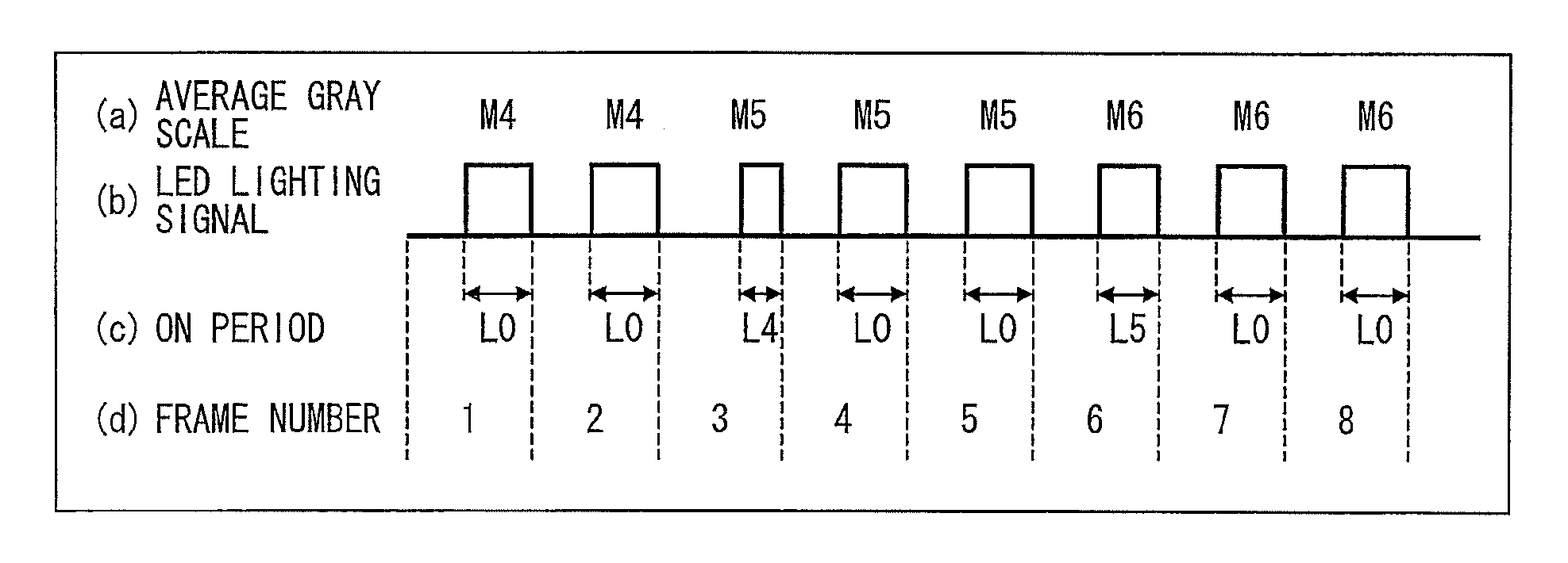
Frame Phase Shift
[0160]As described earlier, a video signal creation section 2 determines a gray scale in an LCD panel 7 and a brightness of an LED 10 in accordance with image data (a video input signal) that is displayed by an LCD 1. Thereafter, data of the gray scale of the LCD panel 7 thus determined is outputted to an LCD module 3 as an LCD video signal, whereas data of the brightness of the LED 10 thus determined is outputted to a backlight module 4 as an LED video signal.
[0161]In order for a gray scale in the LCD panel 7 to be determined, an LCD video signal is created, with use of a buffer memory, by control in a video creation circuit (which is not shown) in the video creation section 2. Thus, there is a time lag between a time when the video creation circuit receives a video input signal and a time when the video creation circuit outputs the LCD video signal. This causes a frame delay. Also, there is a case that the frame delay is caused in a signal process circuit provided...
PUM
 Abstract
Description
Claims
Application Information
 - R&D
- Intellectual Property
- Life Sciences
- Materials
- Tech Scout
- Unparalleled Data Quality
- Higher Quality Content
- 60% Fewer Hallucinations
Browse by: Latest US Patents, China's latest patents, Technical Efficacy Thesaurus, Application Domain, Technology Topic, Popular Technical Reports.
© 2025 PatSnap. All rights reserved.Legal|Privacy policy|Modern Slavery Act Transparency Statement|Sitemap|About US| Contact US: help@patsnap.com