Fuel cell system
a fuel cell and system technology, applied in the field of fuel cells, can solve problems such as deterioration of power generation capacity, and achieve the effect of stable start-up operation
- Summary
- Abstract
- Description
- Claims
- Application Information
AI Technical Summary
Benefits of technology
Problems solved by technology
Method used
Image
Examples
first embodiment
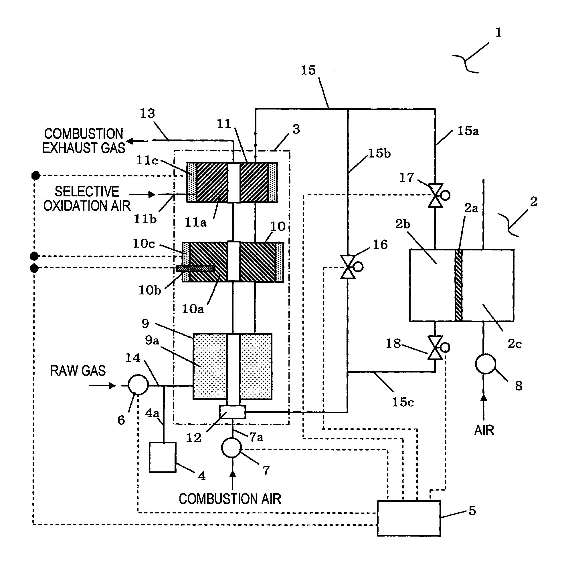
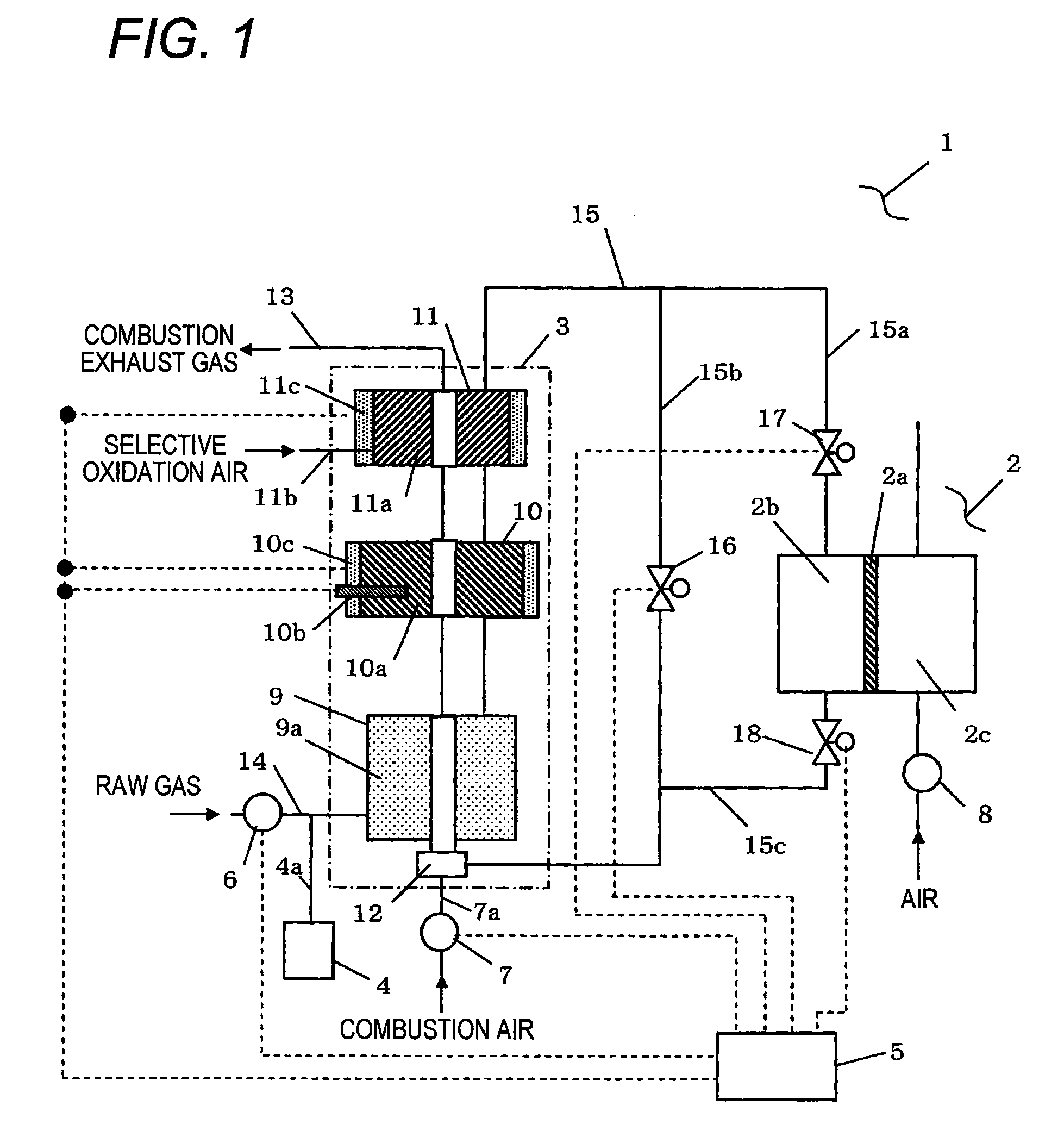
[0058]FIG. 1 is a schematic diagram showing a configuration of a fuel cell system of a first embodiment of the present invention.
[0059]As shown in FIG. 1, a fuel cell system 1 of the present embodiment includes at least a fuel cell 2, a fuel processor 3, a steam generator 4, a control unit 5, a raw gas supply device 6, a combustion air fan 7, and a cathode air blower 8. An LPG is utilized at this time as a raw gas to be supplied to the fuel cell system 1, and an LPG cylinder (not shown) is connected to the raw gas supply device 6 outside the fuel cell system 1. Another hydrocarbon-based material, such as a town gas, can also be used as a raw gas. A sulfur compound added to a hydrocarbon-based material as an odorant is eliminated when the raw gas passes through a desulfurizing unit (not shown) placed at an upstream of the raw gas supply device 6 or between the raw gas supply device 6 and the fuel processor 3.
[0060]The fuel cell 2 has a structure in which a solid polyelectrolyte membr...
second embodiment
[0144]FIG. 8 is a schematic diagram showing a configuration of the fuel cell system 1 of a second embodiment of the present invention. In FIG. 8, elements that are the same as those shown in FIG. 1 are assigned the same reference numerals, and their explanations are omitted here for brevity.
[0145]As shown in FIG. 8, the fuel cell system 1 of the present embodiment differs from the fuel cell system 1 of the first embodiment in that the shift heater and the selective oxidation heater are removed from the shift unit 10 and the selective oxidation unit 11 of the fuel cell system 1.
[0146]Specifically, as shown in FIG. 8, the fuel cell system 1 of the first embodiment partially heats the shift catalyst 10a and the selective oxidation catalyst 11a by means of their heaters. In contrast, the fuel cell system 1 of the second embodiment is configured so as to adjust the amount of heat used for heating the reforming catalyst 9a, the shift catalyst 10a, and the selective oxidation catalyst 11a ...
third embodiment
[0178]FIG. 12 is a schematic view showing a configuration of a fuel cell system of a third embodiment of the present invention. In FIG. 12, elements that are the same as those provided in the fuel cell systems 1 described in connection with the first and second embodiments are assigned the same reference numerals, and their explanations are omitted here for brevity. As shown in FIG. 12, the fuel cell system 1 of the third embodiment differs from the fuel cell system 1 of the first embodiment in that the raw gas channel 15 of the fuel cell system 1 described in connection with the first embodiment is provided with a flow meter 40 that has a mutual circulatory communication with the raw gas channel 15.
[0179]At the start-up operation of the fuel cell system 1, the flow meter 40 measures a total of the flow amount of raw gas supplied from the raw gas supply device 6 and the flow amount of desorbed raw gas desorbed from the catalysts of the fuel processor 3. The combustion gas supplied t...
PUM
| Property | Measurement | Unit |
|---|---|---|
| temperature | aaaaa | aaaaa |
| temperature | aaaaa | aaaaa |
| temperature | aaaaa | aaaaa |
Abstract
Description
Claims
Application Information
 - R&D
- Intellectual Property
- Life Sciences
- Materials
- Tech Scout
- Unparalleled Data Quality
- Higher Quality Content
- 60% Fewer Hallucinations
Browse by: Latest US Patents, China's latest patents, Technical Efficacy Thesaurus, Application Domain, Technology Topic, Popular Technical Reports.
© 2025 PatSnap. All rights reserved.Legal|Privacy policy|Modern Slavery Act Transparency Statement|Sitemap|About US| Contact US: help@patsnap.com


