Fuel cell system
a fuel cell and system technology, applied in electrochemical generators, chemistry apparatuses and processes, sustainable manufacturing/processing, etc., can solve problems such as deterioration of power generation capacity, and achieve the effect of increasing catalyst temperature and stable start-up operation
- Summary
- Abstract
- Description
- Claims
- Application Information
AI Technical Summary
Benefits of technology
Problems solved by technology
Method used
Image
Examples
first embodiment
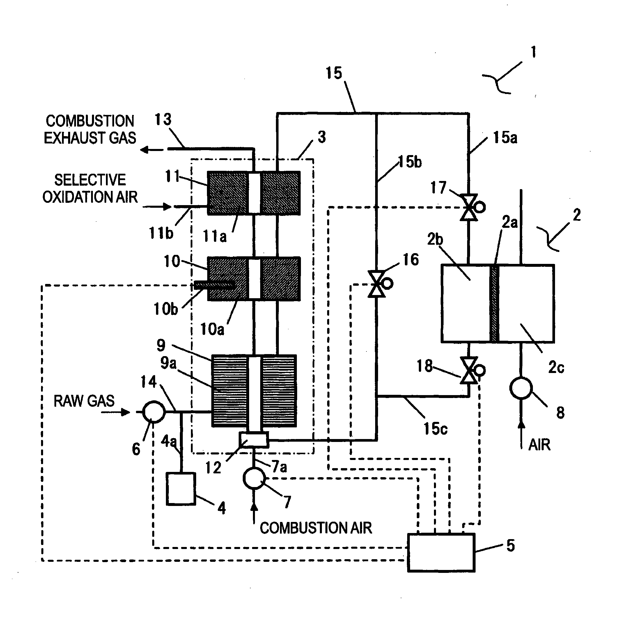
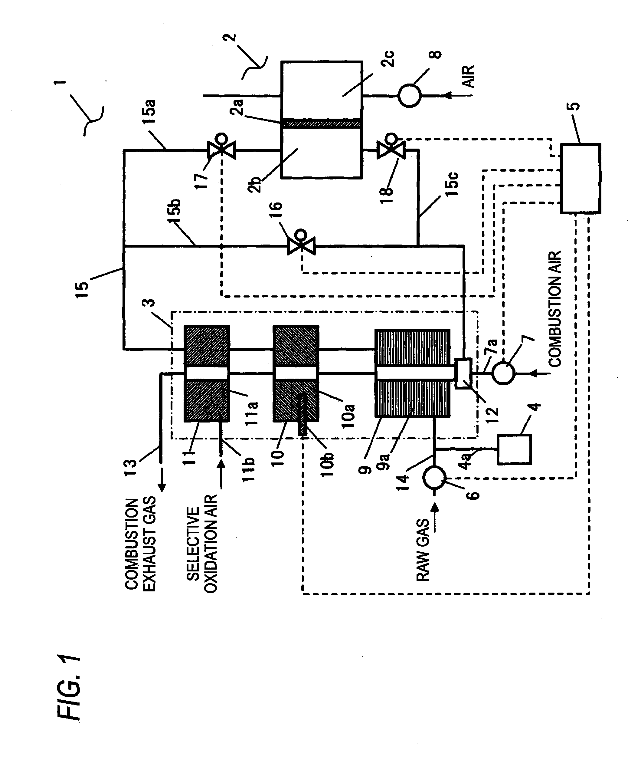
[0055]FIG. 1 is a schematic diagram showing a configuration of a fuel cell system according to a first embodiment of the present invention.
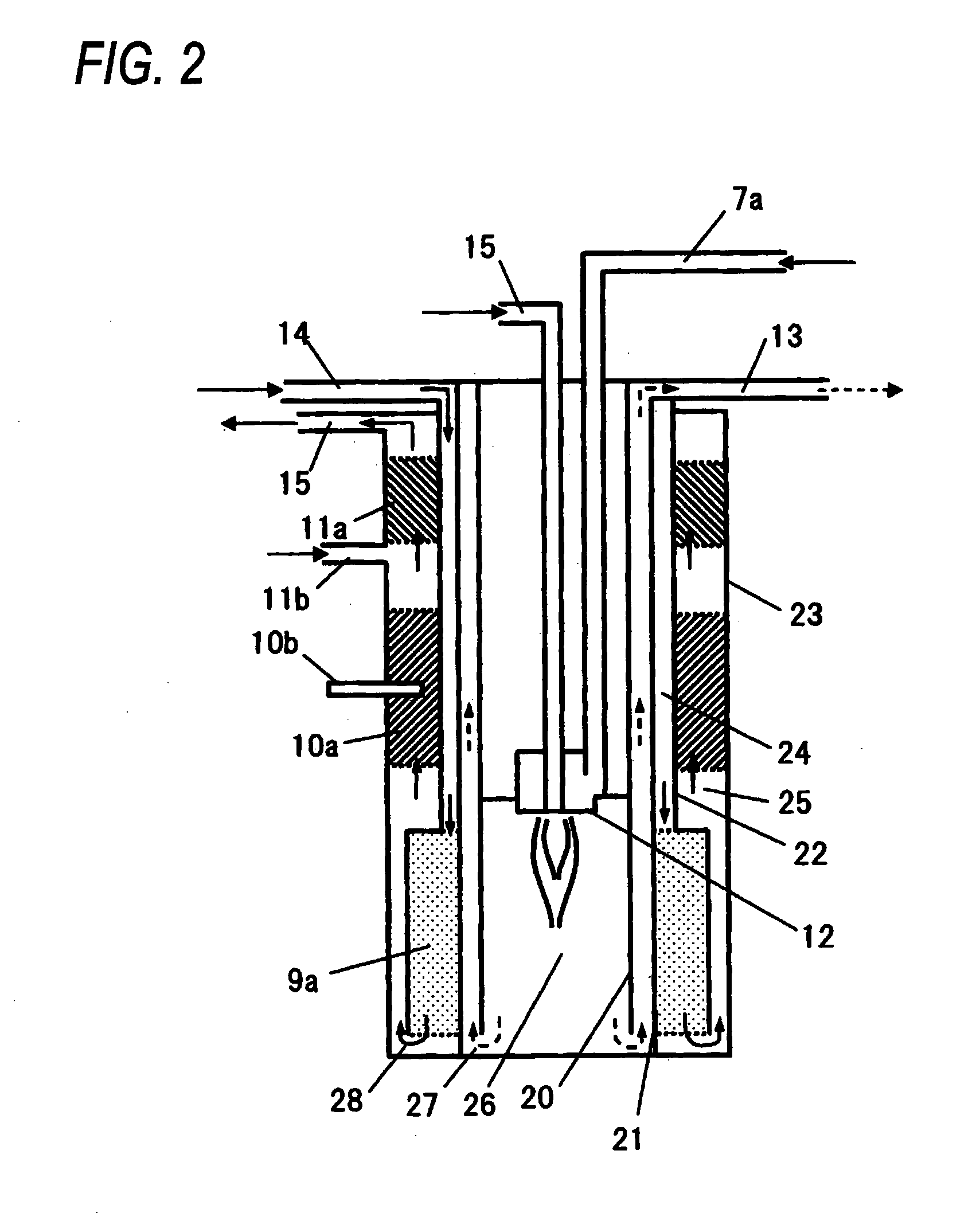
[0056]As shown in FIG. 1, a fuel cell system 1 of an embodiment includes at least a fuel cell 2, a fuel processor 3, a steam generating device 4, a control unit 5, a raw gas supply device 6, a combustion air fan 7, and a cathode air blower 8. The combustion air fan 7 is an air blower configured to supply combustion air to a burner unit, described later. An LPG is utilized at this time as a raw gas supplied to the fuel cell system 1. An LPG cylinder (not shown) is connected to the raw gas supply device 6 outside of the fuel cell system 1. Another hydrocarbon-based material, such as a town gas, may also be used as the raw gas. A sulfur compound added to a hydrocarbon-based material as an odorant is eliminated when the raw gas passes through a desulfurization unit (not shown) placed at an upstream of the raw gas supply device 6 or between the raw ga...
second embodiment
[0122]FIG. 7 is a schematic diagram showing a configuration of the fuel cell system 1 of a second embodiment of the present invention. In FIG. 7, constituent elements that are the same as those shown in FIG. 1 are assigned the same reference numerals, and their explanations are omitted here for brevity.
[0123]As shown in FIG. 7, the fuel cell system 1 of the present embodiment differs from the fuel cell system 1 of the first embodiment in that a shift unit 30 of the fuel cell system 1 described in connection with the first embodiment is provided with a shift heater 31 and that a selective oxidation unit 32 is provided with a selective oxidation heater 33.
[0124]As shown in FIG. 7, the fuel cell system 1 of the second embodiment is configured such that the shift heater 31 is provided outside of the shift unit 30 where the shift heater 31 does not contact the shift catalyst 10a and that the selective oxidation heater 33 is provided outside of the selective oxidation unit 32 where the se...
third embodiment
[0154]FIG. 11 is a schematic diagram showing a configuration of the fuel cell system 1 of a third embodiment of the present invention. In FIG. 11, constituent elements that are the same as those of the fuel cell systems 1 described in connection with the first and second embodiments are assigned the same reference numerals, and their explanations are omitted.
[0155]As shown in FIG. 11, the fuel cell system 1 of the third embodiment differs from the fuel cell system described in connection with the first embodiment in that a flow meter 40 through which the raw gas channel 15 runs is disposed in the raw gas channel 15 of the fuel cell system 1 described in connection with the first embodiment.
[0156]At the start-up operation of the fuel cell system 1, the flow meter 40 measures the total amount of raw gas supplied from the raw gas supply device 6 and the desorbed raw gas desorbed from the catalyst of the fuel processor 3. The word “combustion gas supplied to the burner unit 12” at the s...
PUM
| Property | Measurement | Unit |
|---|---|---|
| temperature | aaaaa | aaaaa |
| temperature | aaaaa | aaaaa |
| temperature | aaaaa | aaaaa |
Abstract
Description
Claims
Application Information
 - R&D
- Intellectual Property
- Life Sciences
- Materials
- Tech Scout
- Unparalleled Data Quality
- Higher Quality Content
- 60% Fewer Hallucinations
Browse by: Latest US Patents, China's latest patents, Technical Efficacy Thesaurus, Application Domain, Technology Topic, Popular Technical Reports.
© 2025 PatSnap. All rights reserved.Legal|Privacy policy|Modern Slavery Act Transparency Statement|Sitemap|About US| Contact US: help@patsnap.com


