Autoinjector

a technology of auto-injector and injection device, which is applied in the direction of medical devices, intravenous devices, medical devices, etc., to achieve the effect of significantly reducing the complexity of the auto-injector

Active Publication Date: 2014-06-10
SHL MEDICAL AG
View PDF108 Cites 32 Cited by
  • Summary
  • Abstract
  • Description
  • Claims
  • Application Information

AI Technical Summary

Benefits of technology

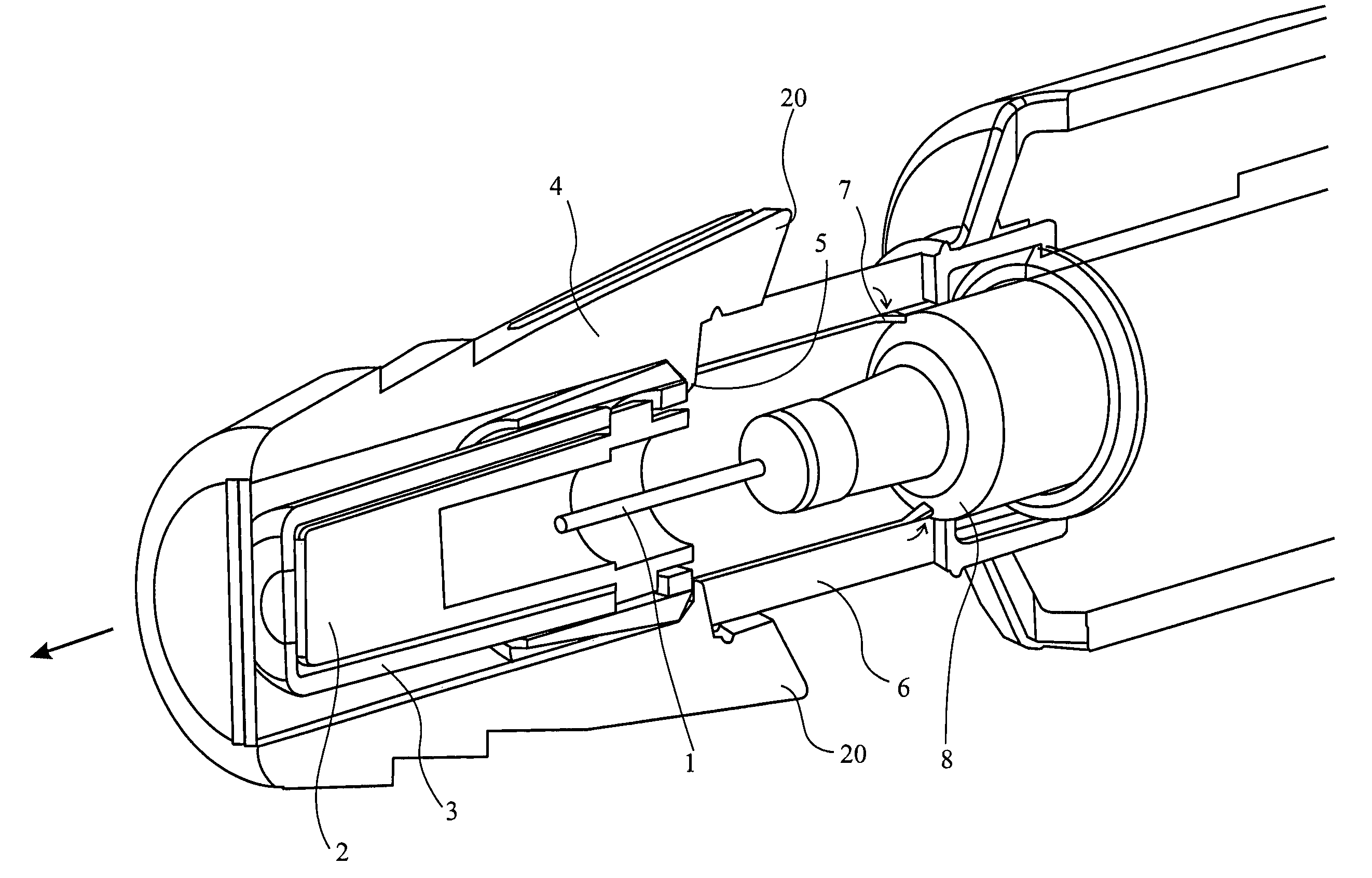
[0016]In one embodiment, said blocking means are movable from said first position to said second position upon removal of a needle cover from said needle and / or removal of an end cap from the front end of the autoinjector. This automatic movement has the advantage of not requiring any positive additional action by the user, other than the normal removal of the autoinjector's end cap.
[0023]an inner housing at least part of which is intermediate said outer housing and said syringe holder,characterised in that one of said inner housing and syringe holder is provided with a gripping means for gripping the other of said inner housing and syringe holder so as to be capable of substantially preventing forward axial movement of the syringe when a forward axial force is applied to said needle, but incapable of preventing forward axial movement of the syringe during actuation of the autoinjector to deliver an injection.
[0024]Preferably, the autoinjector is a single-use autoinjector. The simple construction of the autoinjector makes it very appropriate for applications such as emergency use for injecting a large population to control a pandemic, where a large number of cost-effective disposable autoinjectors are required. A single-use autoinjector also provides a very convenient means for patients to administer their own injections, even if lacking in dexterity and / or experience.
[0026]Preferably, the syringe is axially moveable in said housing and is biased so that the needle is normally wholly inside said housing, wherein before injection the syringe is movable axially so as to move at least a part of said needle out of the housing and wherein after injection, the syringe is able to retract in order to retract said part of said needle into the housing. The concealment of the needle both before and after injection makes the autoinjector particularly suitable where the patient has any aversion to injection by needle. Concealment of the needle both before and after injection also eliminates the risk of needle-stick injury.

Problems solved by technology

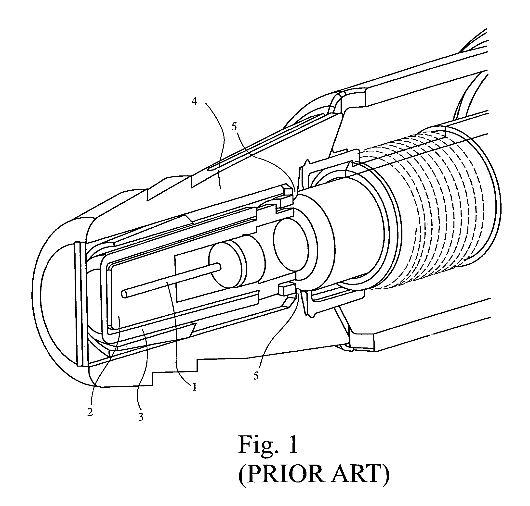
A potential problem arises when the needle cover of an autoinjector is removed, in preparation for delivering an injection.

Method used


Image

  • Autoinjector
  • Autoinjector
  • Autoinjector

Examples


second embodiment

[0050]the invention is illustrated in FIG. 3. FIG. 3 shows a modified inner housing 9 for an autoinjector of the type described in, for example, WO 2005 / 070481. The inner housing 9 is provided with gripping means in the form of one or more barbed hooks 10 at the front end thereof. FIG. 3 shows an inner housing 9 having a generally square cross-sectional shape, but as illustrated in FIG. 4 an inner housing of generally circular cross-sectional shape (as in WO 2005 / 070481) may equally be provided with hooks 10. As shown in FIG. 4, the hooks 10 are designed to grip the finger flange of a syringe barrel and / or to grip the flange seat 11 of a syringe holder of the type described in, for example, WO 2005 / 070481.

first embodiment

[0051]As with the flexible fingers of the first embodiment, the hooks 10 are strong enough to substantially prevent forward axial movement of the barrel and / or syringe holder caused by pulling the rubber moulding from the needle. However, the hooks 10 are not strong enough to resist the axial force supplied by the autoinjector's main energy source. When the autoinjector is actuated for delivery of an injection, the inner housing 9 moves rapidly forwards together with the syringe holder and therefore hooks 10 do not affect the actuation of the device to deliver an injection. In any case, the hooks 10 are relatively weak and capable of being forced radially-outwardly, out of the axial path of the syringe holder.

[0052]In the embodiments illustrated in FIGS. 3 and 4, the gripping means (hooks 10) are located on the inner housing and grip the flange seat of the syringe holder and / or finger flange of the barrel. Alternatively, the gripping means could be located on the flange seat of the ...


PUM


Abstract

An autoinjector comprising an outer housing in which can be mounted a syringe for holding a volume of medicament, the syringe for holding medicament having a needle at one end thereof, a syringe holder for supporting the syringe in an axial position relative to the outer housing, and an intermediate housing at least part of which is located within said outer housing, characterised in that said intermediate housing is provided with a blocking means capable of abutting the syringe or the syringe holder so as to be capable of preventing forward axial movement of the syringe when a forward axial force is applied to said needle before actuation of the autoinjector to deliver an injection, but incapable of preventing forward axial movement of the syringe during actuation of the autoinjector to deliver an injection.

Description

CROSS-REFERENCE TO RELATED APPLICATIONS[0001]This application is a national stage application under 35 U.S.C. 371 of PCT Application No. PCT / GB2007 / 004870 having an international filing date of 18 Dec. 2007, which designated the United States, which PCT application claimed the benefit of Great Britain Application No. 0625169.8 filed 18 Dec. 2006, the entire disclosure of each of which are hereby incorporated herein by reference.[0002]This invention relates to the field of autoinjectors for the administration of liquid medication, for example, interferon.BACKGROUND[0003]An autoinjector is an automatic injection device designed to facilitate delivery of a dose of medicament to a patient through a hypodermic needle, the injection usually being administered by the patient themselves. An autoinjector works, for example, by delivering an injection automatically upon actuation by the patient pressing a button, moving a lever or part of a housing etc. This is in contrast to a conventional m...

Claims


Application Information

Patent Timeline
Patent Type & Authority Patents(United States)
IPC IPC(8): A61M5/20A61M5/315
CPCA61M2005/2073A61M5/3202A61M5/2033A61M5/3204A61M5/20
Inventor STAMP, KEVINCLEATHERO, IAN CHARLES
Owner SHL MEDICAL AG
Why Eureka
Try Eureka