
Input device, terminal equipped with the same, and inputting method

a technology of input device and input terminal, which is applied in the direction of instruments, computing, electric digital data processing, etc., can solve the problems of low portability of methods, user has to get used to inputting, input errors, etc., and achieves the effects of large operating area, high accuracy, and reduced size of detection section on the devi

Active Publication Date: 2014-05-20
NEC CORP
View PDF11 Cites 2 Cited by
  • Summary
  • Abstract
  • Description
  • Claims
  • Application Information

AI Technical Summary

Benefits of technology

The present invention provides an input device that can be used on the human body, with a detection section that can reflect the moving speed and movement of a pointer on the device. This allows for accurate detection of input even with a small detection section. The device is also portable and provides high-accuracy input through a contact with the body, without the need for winding a detection member on the body. The input device includes an input section with multiple detection sections that can detect forces in multiple directions, allowing for precise input in different directions. The input area can be divided into different areas for more precise input. The detection section includes a key top, a parallel plate, and pressure sensors to detect forces in three directions.

Problems solved by technology

However, in the invention of Patent Document 1, as a finger performing inputting operation does not move, it is difficult to check the operation, so that a user has to get used to inputting.
This may cause input errors.
However, as an input section has to be prepared separately from the device, this method does not have a high level of portability, and involves botheration of attaching a detection section to the operator.

Method used


Image

  • Input device, terminal equipped with the same, and inputting method
  • Input device, terminal equipped with the same, and inputting method
  • Input device, terminal equipped with the same, and inputting method

Examples


first embodiment

[First Embodiment]

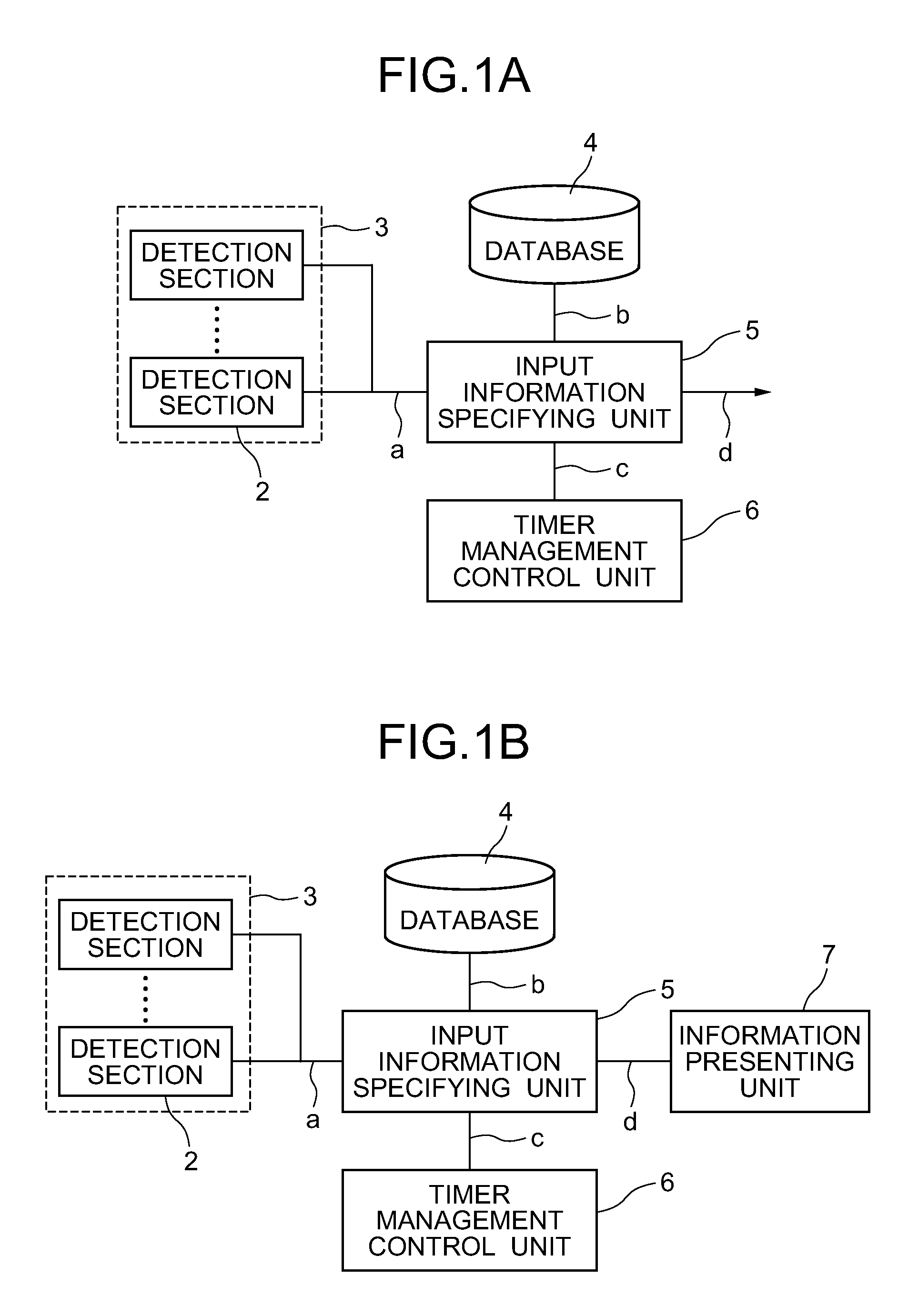
[0016]FIG. 1(a) is a block diagram showing the configuration of an input device according to a first embodiment of the present invention. As shown in FIG. 1(a), the input device of the present embodiment includes an input section 3 disposed at a location contacting a fingertip performing an input and including a plurality of detection sections 2 which output a plurality of pieces of detection data “a” when detects a force; a timer management control section 6 which monitors the detection data “a” and is activated when detecting that an input is performed on the detection section 2 to thereby generate a trigger serving as a timing for detecting an input with certain time intervals and output the trigger as timing data “c”; and an input information specifying means 5 which, upon receiving the detection data “a” and the timing data “c”, converts the detection data “a” into time-series data for each trigger based on the trigger of the timing data “c” and compares the t...

second embodiment

[Second Embodiment]

[0078]FIG. 14 is a block diagram showing the configuration of an input device according to a second embodiment of the present invention. As shown in FIG. 14, the input device of the present embodiment includes, an input section 3 having a plurality of detection sections 2 for detecting a state of pressure distribution generated on a contact surface with a fingertip when being pressed, and outputting detection data “e” which is pressure distribution data output from the detection section 2; a timer management control section 6 which monitors the detection data “e” and is activated when detecting that an input is performed on the detection section 2 to thereby generate a trigger serving as a timing for detecting inputs with certain time intervals and output the trigger as timing data “c”; and an input information specifying means 5 which, upon receiving the detection data “e” and the timing data “c”, compares data converted from the detection data “e” (normalization...

example 1

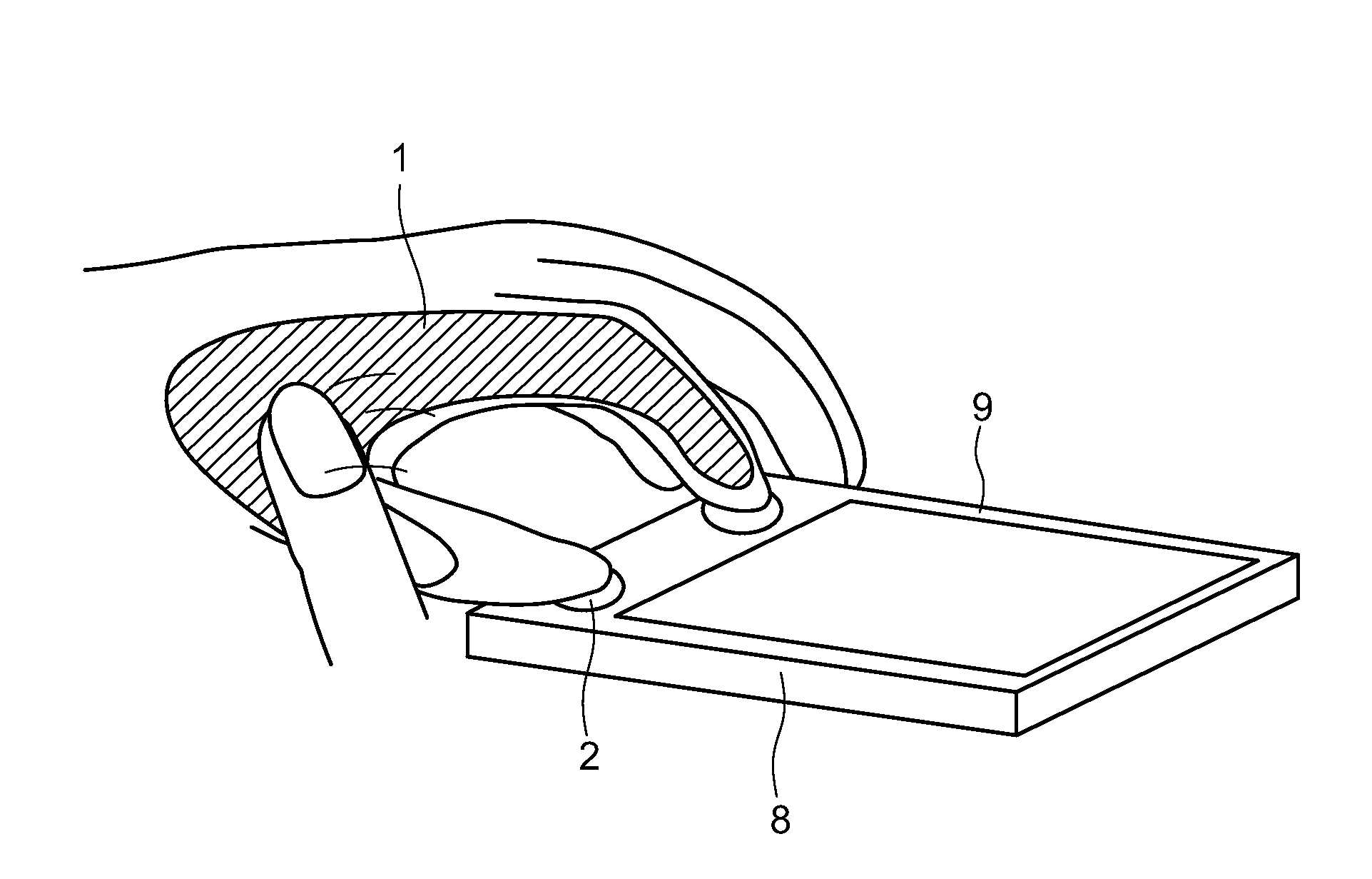
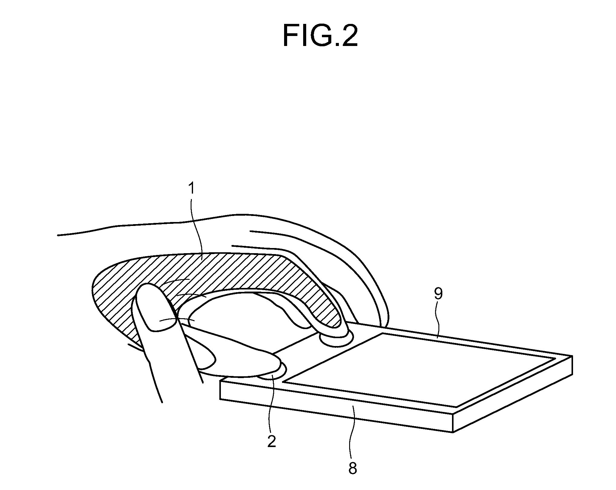
[0100]FIG. 18 is a perspective view showing a state of performing an input to a terminal of an example of the present invention. The present example shows a case where it is difficult to provide a detection section 2 for detecting an input on the same plane as a display section because of a large display screen. The present example describes the case of applying the present invention to a full-screen terminal (Examples 2 and 3 also show the cases of applying the present invention to a full-screen terminal). In the present example, the detection section 2 is provided to a side of the device, and a tracing operation to each finger is performed by holding the device in a wrapping manner from the backside. In FIG. 18, a tracing operation is indicated by arrows (also in FIGS. 19 and 20). Identification of such a tracing operation may be used as a page forwarding function of electronic books and the like. In that case, it is only necessary to provide the detection section 2 at a location ...


PUM


Abstract

An input device includes an input section having a detection section which detects a force transmitted via a human body when a trailing operation is performed on a part of the body contacting the input device, and outputs the force as detection data “a”; a timer management control unit which generates a timing for converting the detection data “a” into time-series data and outputs the timing as timing data “c”; an input information specifying unit which converts the detection data “a” into time-series data based on the timing data “c”, compares the time-series data with stored data “b” in a database which has been set beforehand, to thereby specify an input operation and output the input operation as input information specifying data “d”; and an information presenting unit which, upon receiving the input information specifying data “d”, displays a function assigned to the input operation.

Description

TECHNICAL FIELD[0001]The present invention relates to an input device and an inputting method, applicable to mobile devices such as mobile phones, PDAs, and laptop PCs.BACKGROUND ART[0002]As input devices used in mobile devices focused on portability or on display units, those having a smaller input section on the device are required.[0003]One method for reducing the space of an input section on a device is to detect finger pressures in X, Y, and Z directions to thereby perform pointing or text inputting operation. In an example of this method, track points are used, and handwriting text inputting is performed according to the finger pressure varying pattern thereof (see Patent Document 1, for example). However, in the invention of Patent Document 1, as a finger performing inputting operation does not move, it is difficult to check the operation, so that a user has to get used to inputting. This may cause input errors.[0004]In another method, a detection unit is separated from a dev...

Claims


Application Information

Patent Timeline
Patent Type & Authority Patents(United States)
IPC IPC(8): G09G5/08G06F3/0338G06F3/041G06F3/0354G06F3/033
CPCG06F3/0414G06F3/011G06F3/0338G06F3/03547
Inventor NORIEDA, SHIN
Owner NEC CORP
Learn More