Method for operating an internal combustion engine

a technology of internal combustion engine and oil consumption, which is applied in the direction of combustion engine, crankcase ventillation, machine/engine, etc., can solve the problems of significant additional cost, significant increase in oil consumption, and high lubricant consumption of internal combustion engine in operating phases with low absolute, so as to reduce the pressure in the crankcase and reduce the lubricant consumption. , the effect of reducing the lubricant consumption

Inactive Publication Date: 2014-05-20
AUDI AG
View PDF15 Cites 1 Cited by
  • Summary
  • Abstract
  • Description
  • Claims
  • Application Information

AI Technical Summary

Benefits of technology

[0005]To this end, a method for operating an internal combustion engine is proposed, wherein the internal combustion engine has a crankcase, a crankcase vent and an intake system. To reduce the lubricant consumption of the internal combustion engine, the pressure in the crankcase should be reduced from a differential pressure between the intake system and the crankcase to maximally −500 mbar, in particular maximally −300 mbar, with respect to ambient pressure. According to the invention, the crankcase pressure is reduced to maximally −500 mbar, in particular maximally −300 mbar, with respect to ambient pressure during the operation of the internal combustion engine, preferably in operating state with zero load or in a deceleration phase. The crankcase is therefore under reduced pressure such that the differential pressure to the pressure in the intake manifold is smaller in order to prevent a critical differential pressure. The intake manifold pressure corresponds approximately to the pressure in the combustion chamber above the piston when the intake valves are open.
[0006]In a preferred embodiment of the method, the pressure in the crankcase is reduced when the differential pressure between the intake manifold and the crankcase exceeds at least a predetermined threshold value. If the differential pressure between the intake system, in the simplest case between the intake manifold and the crankcase, becomes too large because the vacuum of the intake system is too high in relation to the crankcase, then the pressure in the crankcase is also reduced, thereby reducing the differential pressure.
[0008]In a preferred embodiment of the method, the pressure in the crankcase is adjusted in a range from −50 mbar to −500 mbar, in particular in a range from −100 mbar to −300 mbar with respect to the environment. This setting of the crankcase pressure relative to the ambient pressure enables operation in a safe range with respect to lubricant consumption for known pressures of the intake system, in particular intake manifold pressures. The crankcase pressure relative to the ambient pressure can be relatively easily adjusted. This produces a differential pressure to the intake system, in particular to the intake manifold, in a certain interval relative to the respective operating pressure of the intake system and the intake manifold, respectively.

Problems solved by technology

It is known from online oil consumption measurement that internal combustion engines have high oil consumption in operating phases with low absolute intake tube pressure, corresponding to a very high intake tube vacuum.
For example, if a differential pressure of about 650 mbar is exceeded, a large increase in the oil consumption is observed.
However, this entails significantly more stringent requirements for precision and significant additional costs as well as increased friction losses of the sealing piston rings and pistons.

Method used


Image

  • Method for operating an internal combustion engine
  • Method for operating an internal combustion engine
  • Method for operating an internal combustion engine

Examples


Embodiment Construction

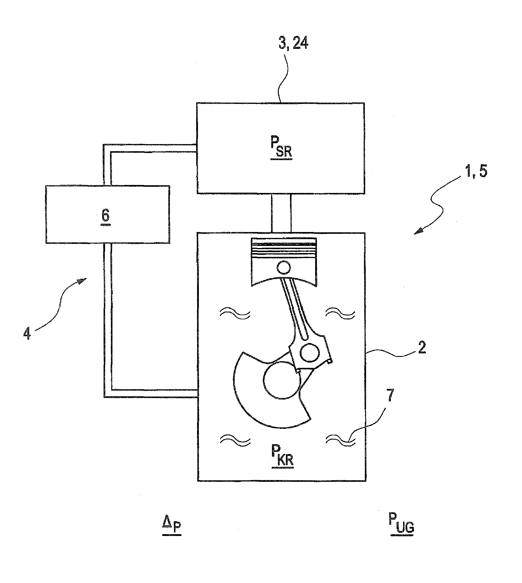
[0015]FIG. 1 shows schematically an internal combustion engine 1 with a crankcase 2 and an intake manifold 3 forming an intake system 24, through which combustion air is supplied to the internal combustion engine 1. The crankcase 2 and the intake manifold 3 are connected with each other by a crankcase vent 4. In the illustrated embodiment, the internal combustion engine 1 is constructed as a naturally-aspirated wet sump engine 5. The crankcase vent 4 includes a pressure control valve 6 which allows adjustment of the vacuum pressure PKR in the crankcase 2 by applying to the crankcase 2 an intake manifold vacuum PSR, which can be adjusted with the pressure control valve 6 in the intake manifold 3, thereby evacuating lubricant vapors 7 residing in the crankcase 2. The pressure control valve 6 is hereby configured such that a differential pressure Δp between the crankcase vacuum PKR and the ambient pressure PUG can be adjusted to be between 100 mbar in 300 mbar. The crankcase therefore ...


PUM


Abstract

The invention relates to a method for operating an internal combustion engine with a crankcase, a crankcase vent and an intake system. According to the invention, the pressure in the crankcase can be reduced, depending on a differential pressure between the intake system and the crankcase, to maximally −500 mbar, in particular maximally −300 mbar, with respect to ambient pressure for reducing lubricant consumption of the internal combustion engine.

Description

CROSS-REFERENCES TO RELATED APPLICATIONS[0001]This application is the U.S. National Stage of International Application No. PCT / EP2009 / 008731, filed Dec. 8, 2009, which designated the United States and has been published as International Publication No. WO 2010 / 075935 and which claims the priority of German Patent Application, Serial No. 10 2008 061 057.7, filed Dec. 8, 2008, pursuant to 35 U.S.C. 119(a)-(d).BACKGROUND OF THE INVENTION[0002]The invention relates to a method for operating an internal combustion engine with a crankcase, a crankcase vent and an intake system.[0003]Vehicles with modern internal combustion engines have a crankcase vent which prevents leakage of lubricants, preferably oil or lubricant vapors, into the environment. In the simplest case, the crankcase vent consists only of a tube or hose connection between the crankcase and an intake tube of the internal combustion engine, wherein the vacuum in the intake tube suctions lubricant vapors in the crankcase. Depe...

Claims


Application Information

Patent Timeline
Patent Type & Authority Patents(United States)
IPC IPC(8): F01M13/00
CPCF01M13/023F01M2013/0005
Inventor INGELFINGER, UDOROSENBACK, MATTHIAS
Owner AUDI AG
Why Eureka
Try Eureka