Image forming apparatus and method for controlling the same

a technology of image forming apparatus and control method, which is applied in the direction of optics, instruments, electrography/magnetography, etc., can solve the problems of uneven image quality, uneven lubricant amount on image carrier, etc., and achieve the effect of reducing lubricant consumption, inhibiting image unevenness, and reducing lubricant consumption

Active Publication Date: 2017-04-27
KONICA MINOLTA INC
View PDF5 Cites 0 Cited by
  • Summary
  • Abstract
  • Description
  • Claims
  • Application Information

AI Technical Summary

Benefits of technology

[0016]The present disclosure has been made to solve the above-mentioned problems, and according to one aspect, it is an object of the present invention to provide an image forming apparatus for reducing lubricant consumption while inhibiting image unevenness caused by a difference in amount of lubricant on an image carrier. According to another aspect, it is an object of the present invention to provide a control method with which lubricant consumption can be reduced, while inhibiting image unevenness caused by a difference in amount of lubricant on an image carrier.

Problems solved by technology

Therefore, even if the lubricant is uniformly applied over the image carrier, the amount of lubricant may be not uniform on the image carrier.
This difference exceeds an allowable width W not causing the image unevenness, so that the image unevenness is caused.

Method used


Image

  • Image forming apparatus and method for controlling the same
  • Image forming apparatus and method for controlling the same
  • Image forming apparatus and method for controlling the same

Examples


first embodiment

Image Forming Apparatus 100

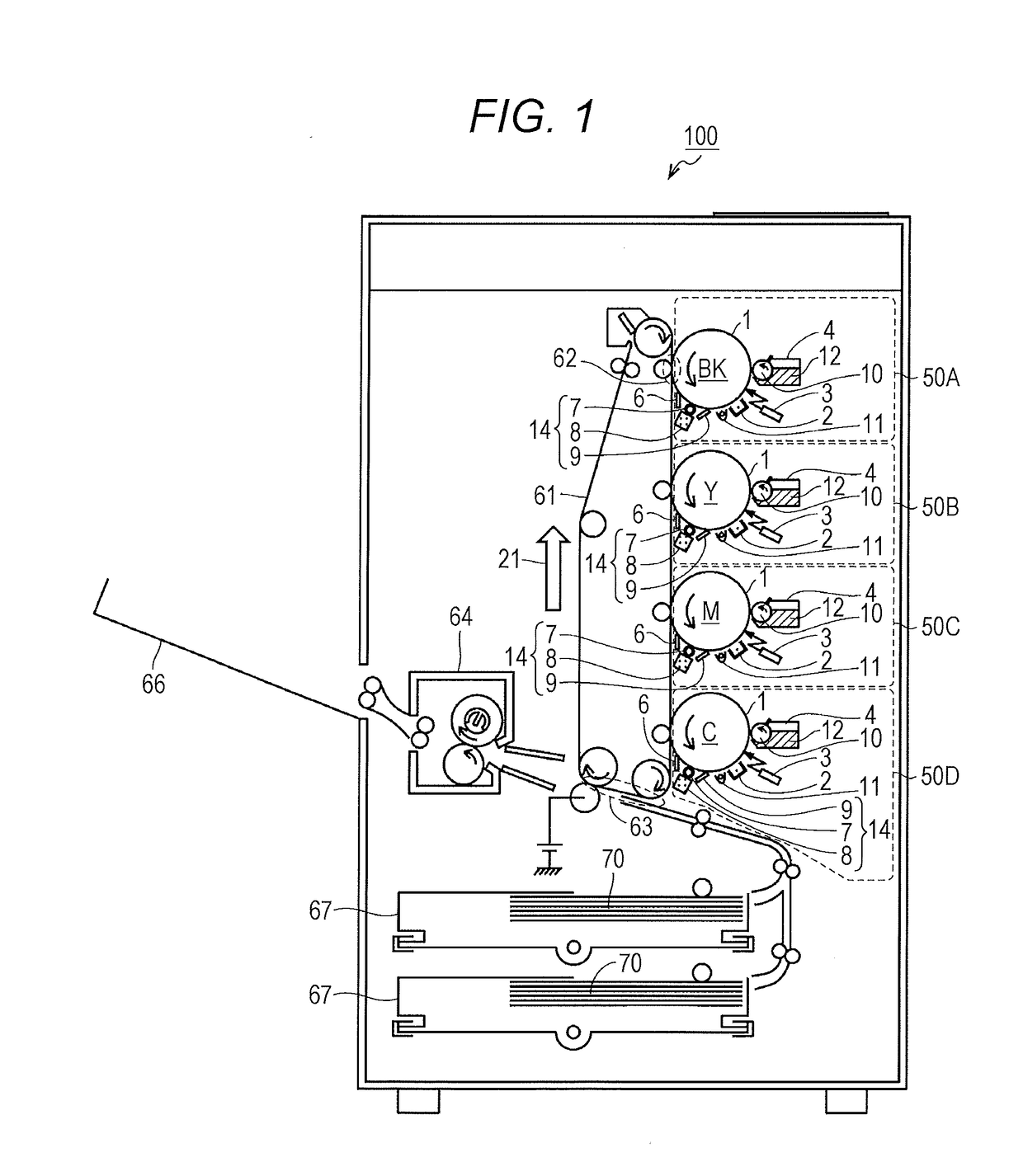
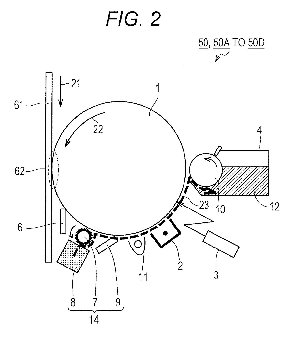
[0045]With reference to FIGS. 1 and 2, a configuration of an image forming apparatus 100 according to a first embodiment will be described. FIG. 1 is an exemplary diagram illustrating an internal configuration of the image forming apparatus 100. FIG. 2 is an exemplary diagram illustrating an internal configuration of an image forming unit 50.

[0046]As illustrated in FIG. 1, the image forming apparatus 100 includes image forming units 50A to 50D, an intermediate transfer belt 61, a primary transfer unit 62, a secondary transfer unit 63, a fuser 64, a tray 66, and cassettes 67.

[0047]The image forming unit 50A forms a black (BK) toner image. The image forming unit 50B forms a yellow (Y) toner image. The image forming unit 50C forms a magenta (M) toner image. The image forming unit 50D forms a cyan (C) toner image. The image forming units 50A to 50D are sequentially disposed along a rotation direction of the intermediate transfer belt 61 (direction indicated by...

second embodiment

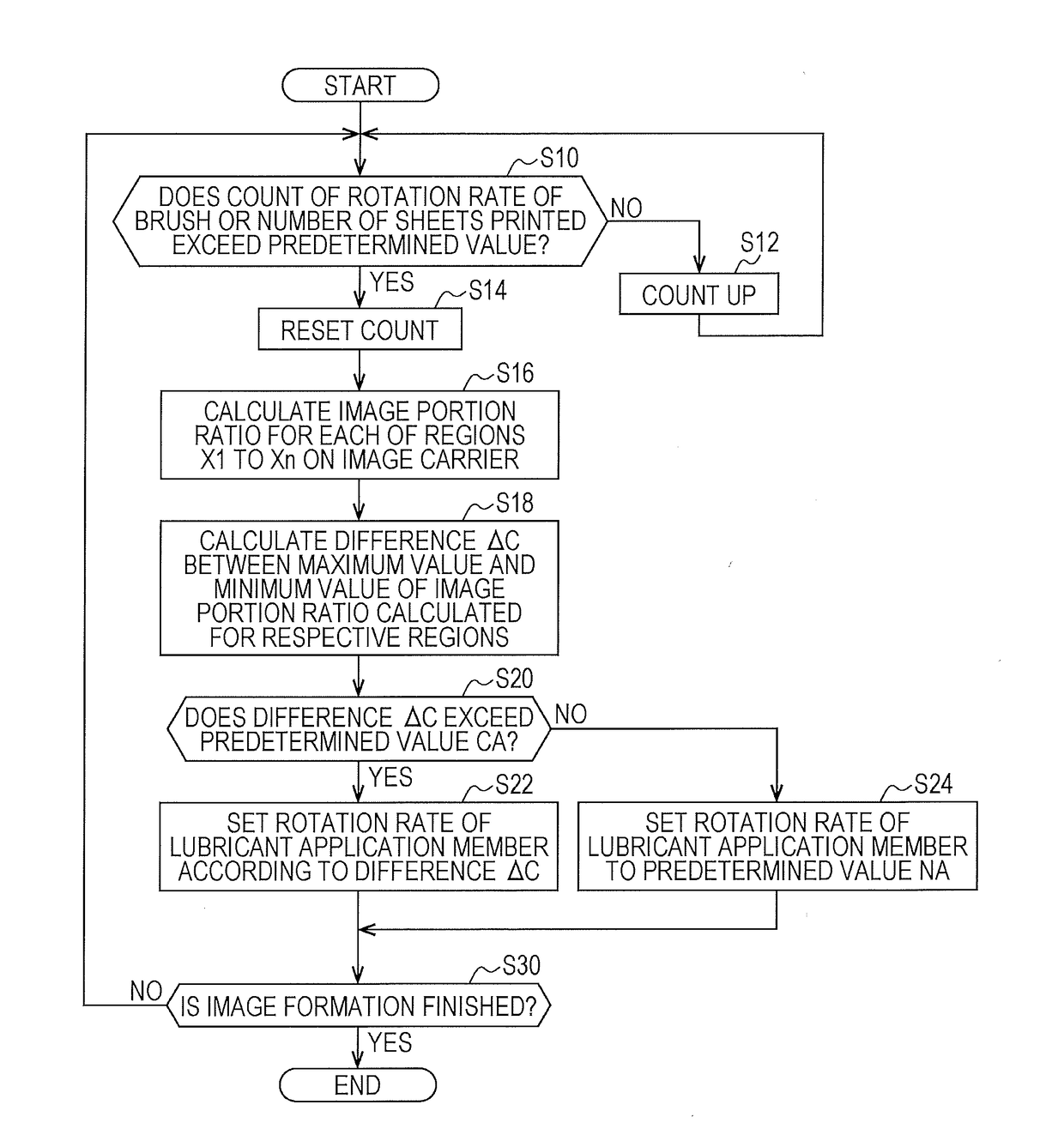
[0127]The image forming apparatus 100 according to the first embodiment is configured so that when a difference ΔC between the maximum value Cmax and the minimum value Cmin of the image portion ratio of respective regions of the image carrier 1 is less than the predetermined value CA (see FIG. 7), the rotation rate of the lubricant application member 7 is maintained constant to the rotation rate NA (see FIG. 7), without causing the fixation of toner onto the image carrier 1. In contrast, an image forming apparatus 100 according to a second embodiment is configured so that when the difference ΔC is less than the predetermined value CA, the rotation rate of the image carrier 1 is reduced according to the maximum value Cmax of the image portion ratio. Therefore, lubricant consumption can be further reduced.

[0128][Method of Controlling Amount of the Lubricant Applied]

[0129]A method of controlling the amount of the lubricant applied, according to the second embodiment will be described w...


PUM


Abstract

An image forming apparatus includes: a rotatable image carrier; an image forming unit configured to form an electrostatic latent image on the image carrier based on information defining at least one of a toner region and a non-toner region; a development unit configured to develop the electrostatic latent image as a toner image; a cleaning unit configured to remove toner remaining on the image carrier, after transfer of the toner image; an application unit configured to apply lubricant on the image carrier; and a hardware processor configured to control an amount of the lubricant applied, calculate a ratio of a toner region for each of regions obtained by dividing a surface of the image carrier in a direction perpendicular to a rotation direction of the image carrier, and control the amount of the lubricant applied according to a difference between a maximum value and a minimum value of the ratio.

Description

[0001]The entire disclosure of Japanese Patent Application No. 2015-209716 filed on Oct. 26, 2015 including description, claims, drawings, and abstract are incorporated herein by reference in its entirety.BACKGROUND OF THE INVENTION[0002]Field of the Invention[0003]The present disclosure relates to a control of an image forming apparatus, and in particular relates to a control of an electrophotographic image forming apparatus.[0004]Description of the Related Art[0005]Electrophotographic image forming apparatuses have been widely used. The electrophotographic image forming apparatuses each perform a printing process including the steps of rotating an image carrier while uniformly charging the image carrier, exposing the image carrier to form an electrostatic latent image, applying toner to the electrostatic latent image on the image carrier, transferring a toner image on the image carrier to an object on which printing is to be performed, removing the toner remaining on the image car...

Claims


Application Information

Patent Timeline
Patent Type & Authority Applications(United States)
IPC IPC(8): G03G21/00
CPCG03G21/0094
Inventor MAEYAMA, TAKESHI
Owner KONICA MINOLTA INC
Why Eureka
Try Eureka