Eureka AIR delivers breakthrough ideas for toughest innovation challenges, trusted by R&D personnel around the world.

Optical fiber, optical fiber cord, and optical fiber cable

a technology of optical fiber and optical fiber cord, which is applied in the direction of optical fiber with multi-layer core/cladding, optical waveguide light guide, instruments, etc., can solve the problems of difficult to provide a sufficient level of osnr and relative large transmission loss, and achieve the effect of small transmission loss

Active Publication Date: 2014-05-13
SUMITOMO ELECTRIC IND LTD
View PDF11 Cites 5 Cited by
  • Summary
  • Abstract
  • Description
  • Claims
  • Application Information

AI Technical Summary

Benefits of technology

The trench optical fiber in this patent has the advantage of being able to transmit light with very low loss.

Problems solved by technology

The trench optical fiber disclosed by Patent Literature 1, however, has a relatively large transmission loss, making it difficult to provide a sufficient level of OSNR.

Method used


Image

  • Optical fiber, optical fiber cord, and optical fiber cable
  • Optical fiber, optical fiber cord, and optical fiber cable
  • Optical fiber, optical fiber cord, and optical fiber cable

Examples


Embodiment Construction

[0017]Embodiments of the present invention will now be described in detail with reference to the accompanying drawings. In the description of the drawings, the identical reference numerals denote same elements, and redundant description is omitted.

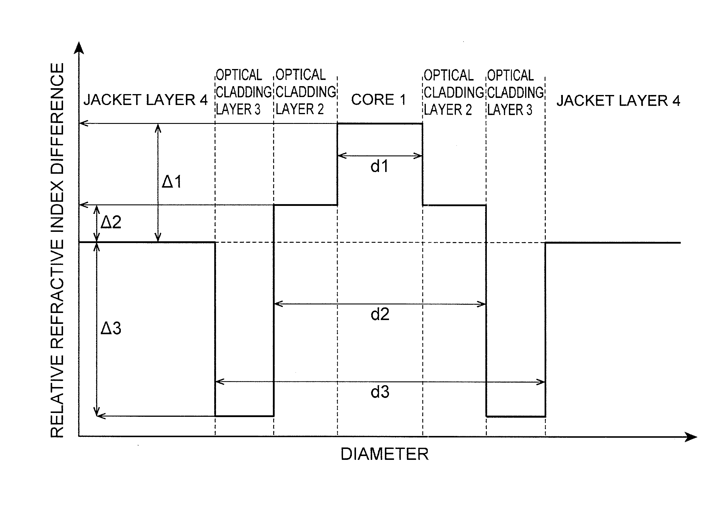
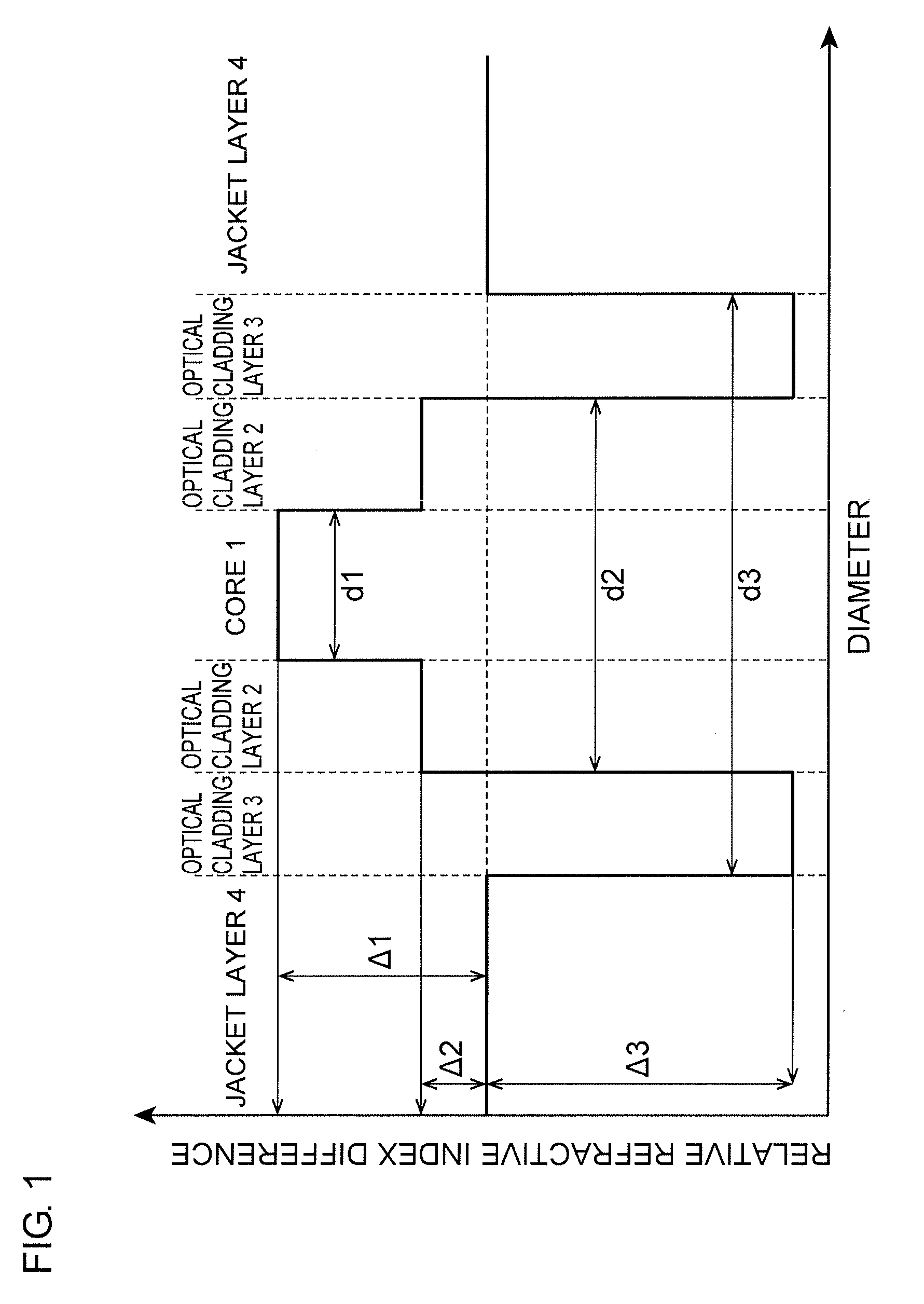
[0018]FIG. 1 is a conceptual diagram illustrating a refractive index profile of an optical fiber according to the present invention. The optical fiber according to the present invention includes a core 1 extending in the axial direction while containing the axial center of the fiber, a first optical cladding layer 2 surrounding the core 1, a second optical cladding layer 3 surrounding the first optical cladding layer 2, and a jacket layer 4 surrounding the second optical cladding layer 3.

[0019]Taking the refractive index of the jacket layer 4 as a reference, the relative refractive index difference of the core 1 is denoted by Δ1, the relative refractive index difference of the first optical cladding layer 2 is denoted by Δ2, and the relati...


PUM


Abstract

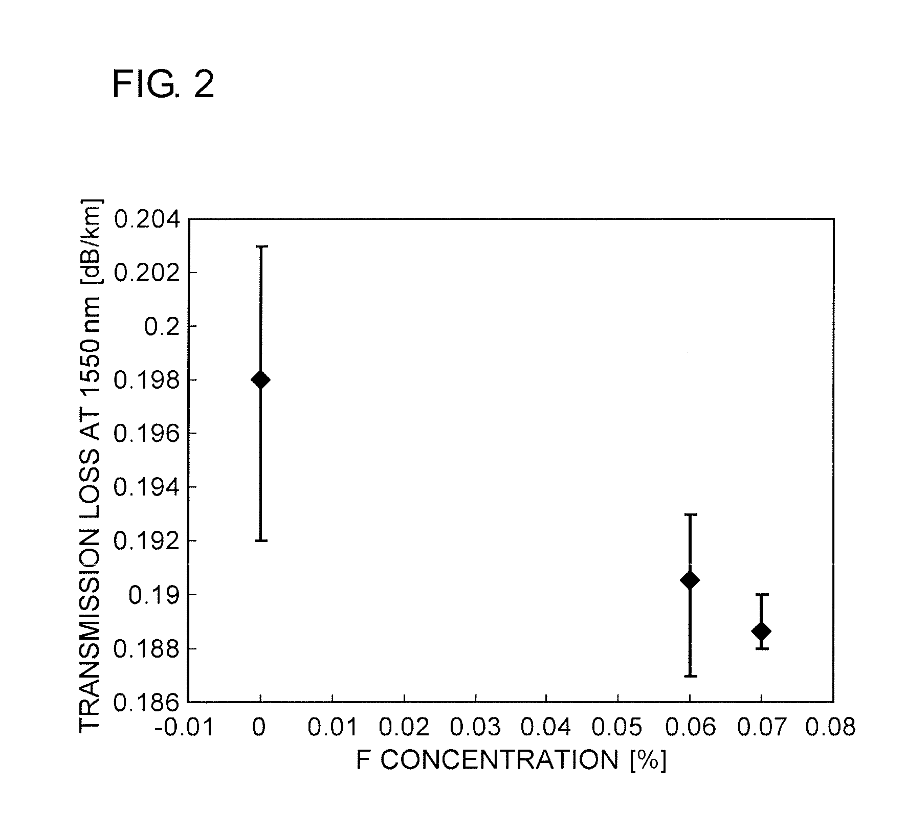
A trench optical fiber that stably realizes a small transmission loss includes (1) a core extending in an axial direction while containing an axial center of the fiber, the core having a diameter d1 of 7.0 μm to 7.4 μm; (2) a first optical cladding layer surrounding the core and having an outside diameter d2 of 1.67d1 to 2.5d1; (3) a second optical cladding layer surrounding the first optical cladding layer; and (4) a jacket layer surrounding the second optical cladding layer and containing fluorine having a concentration of 0.06 wt % or higher. A relative refractive index difference Δ1 of the core with respect to the jacket layer is 0.31% to 0.37%. A relative refractive index difference Δ2 of the first optical cladding layer with respect to the jacket layer is +0.02% or larger and smaller than Δ1. A relative refractive index difference Δ3 of the second optical cladding layer with respect to the jacket layer is −0.2% or smaller.

Description

TECHNICAL FIELD[0001]The present invention relates to an optical fiber, an optical fiber cord, and an optical fiber cable.BACKGROUND ART[0002]International Publication No. 2004 / 092794 (Patent Literature 1) discloses an optical fiber including a core (with a radius r1 and a relative refractive index difference Δ1) extending in the axial direction while containing the axial center of the fiber, a first optical cladding layer (with a radius r2 and a relative refractive index difference Δ2) surrounding the core, a second optical cladding layer (with a radius r3 and a relative refractive index difference Δ3) surrounding the first optical cladding layer, and a jacket layer surrounding the second optical cladding layer. The relative refractive index differences Δ1 to Δ3 satisfy a relationship of Δ1>Δ2>Δ3. Such a refractive index structure is called trench structure. A trench optical fiber has a small bending loss and has been suitably used as an optical transmission line for fiber to...

Claims


Application Information

Patent Timeline
Patent Type & Authority Patents(United States)
IPC IPC(8): G02B6/02
CPCG02B6/0365G02B6/03638
Inventor KONISHI, TATSUYANAKANISHI, TETSUYAHAYASHI, TETSUYA
Owner SUMITOMO ELECTRIC IND LTD
Why Eureka
Eureka Blog
Learn More