
Spine fixation device containing set screw having double spiral form

a fixation device and spiral form technology, applied in the field of spine fixation devices containing set screws having spiral forms, can solve the problems of spine not being stably corrected, limit to maintenance of self-locking, etc., and achieve the effect of stably correcting the spin

Inactive Publication Date: 2014-05-06
KIM MIN SEOK
View PDF3 Cites 0 Cited by
  • Summary
  • Abstract
  • Description
  • Claims
  • Application Information

AI Technical Summary

Benefits of technology

The present invention improves the way vertebral fixation screws and set screws are fastened, making them stronger and more effective. This prevents movement of the spinal rod when adjusting the vertebral position, resulting in a more stable correction.

Problems solved by technology

A patient with a spine partly damaged as described above cannot perform activities necessary for his personal life under such a condition, and even if the extent of damage is not so severe, the damaged part of the spine may be pressed or touched by other adjacent parts to cause pain.
Because of that, there occurs a gap between the screw thread surface of the male screw of the set screw and the screw thread surface of the female screw of the pedicle fixation screw, so there is a limit to maintenance of self-locking.
Accordingly, there is a problem that the spine cannot be stably corrected because the movement of the spinal rod increases.

Method used


Image

  • Spine fixation device containing set screw having double spiral form
  • Spine fixation device containing set screw having double spiral form
  • Spine fixation device containing set screw having double spiral form

Examples


Embodiment Construction

[0038]Hereinafter, exemplary embodiments of the present invention will be described in detail below with reference to the accompanying drawings.

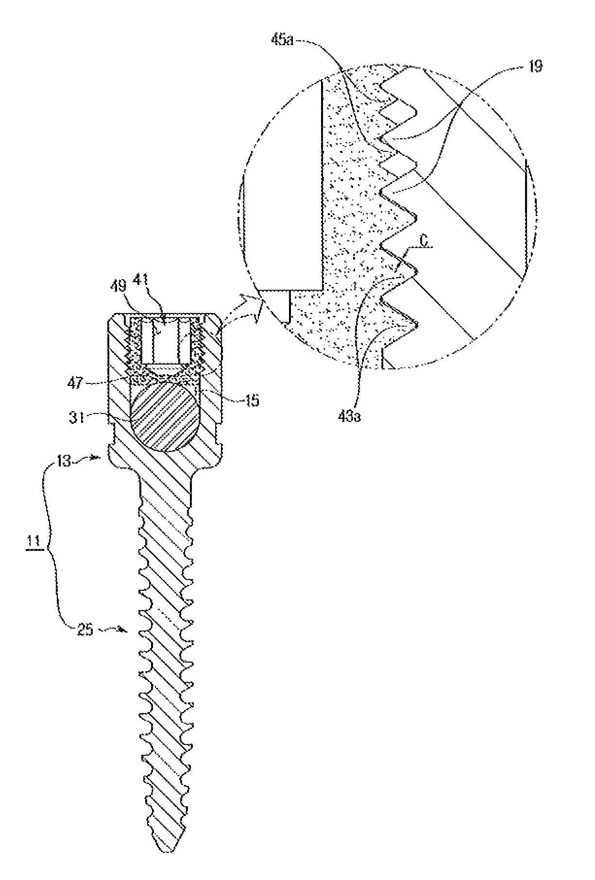
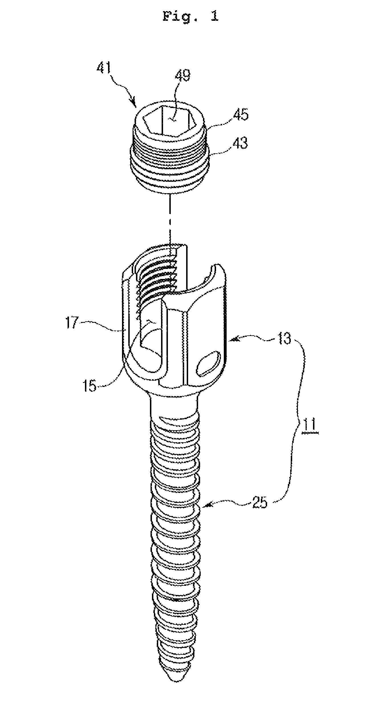
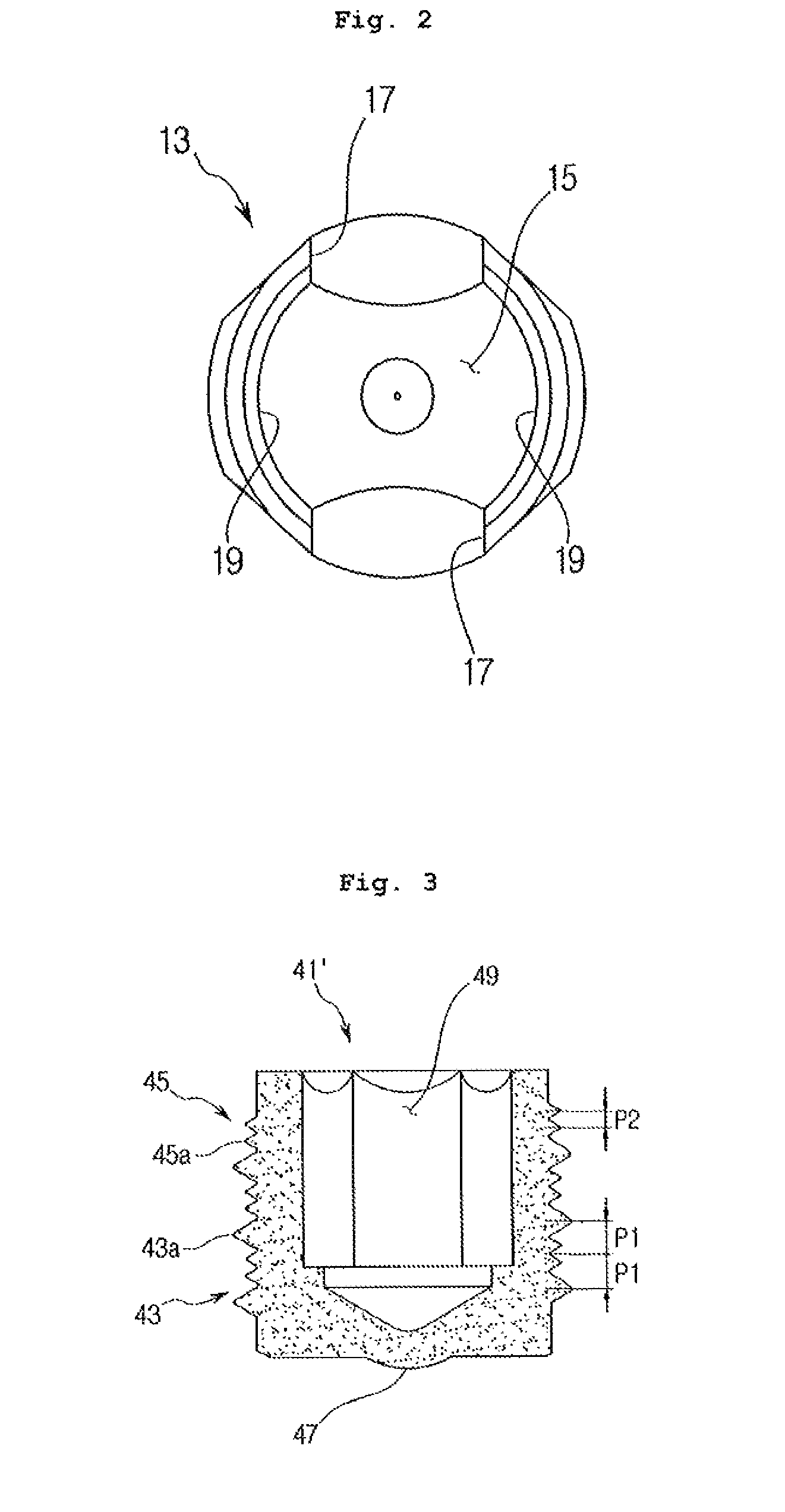
[0039]FIGS. 1 to 5 illustrate a pedicle fixation screw containing a set screw having a spiral form according to the present invention. As shown in these drawings, the pedicle fixation screw containing a set screw having a spiral form according to the present invention includes a pedicle fixation screw 11, a spinal rod 31 which connects a plurality of the pedicle fixation screws 11 to realign the angle and interval of the pedicle, and a set screw 41 which is screw-coupled to the pedicle fixation screw 11.

[0040]The pedicle fixation screw 11 has a head portion 13 in which a receiving groove 15 with a certain depth is formed, and a screw portion 25 which is extended lengthwise from one side of the head portion 13.

[0041]A pair of cut portions 17 are formed in the head portion 13 so that the spinal rod 31 can be easily received in the receiving gr...


PUM


Abstract

The present invention relates to a spine fixation device containing a set screw having a double spiral form. The spine fixation device is characterized by comprising: a pedicle fixation screw which has a head portion having a receiving groove of a certain depth formed thereinside and a plurality of female screws formed in one region of the inner circumference of the receiving groove, and a screw portion extended from one side of the head portion lengthwise and embedded into a pedicle, and is fixed to a damaged pedicle; a spine rod which is received in the receiving groove to connect the pedicle fixation screw, thereby realigning the angle and interval of the pedicle; and a set screw which forms a plurality of male screws with the same screw inner diameter, the same screw thread direction and different pitches, and is screw-coupled to the female screws of the pedicle fixation screw to prevent the movement of the rod received in the receiving groove. Therefore, the fastening force of the pedicle fixation screw and the set screw is increased, the movement of the spine rod is prevented in case of the realignment of the pedicle, and a spine can be realigned stably.

Description

CROSS REFERENCE TO RELATED APPLICATIONS[0001]This application claims the priority of International Application PCT / KR2009 / 003962, filed Jul. 17, 2009, which claims the priority of Korean application number 10-2009-0038346, filed Apr. 30, 2009, both of which are incorporated herein by reference.TECHNICAL FIELD[0002]The present invention relates to a spine fixation device containing a set screw having a double spiral form, and more specifically to a spine fixation device containing a set screw having a double spiral form with an improved screw fastening structure of a pedicle fixation screw and set screw.BACKGROUND ART[0003]The human spine consists of 24 bones, which are engaged with each other in joint forms and can support the axial load even in a bent condition. A plurality of discs are arranged between bones to function as a buffer.[0004]The spine has a structure of various names according to the anatomical profile, and in general it has a form bent in an “S” letter shape.[0005]Sp...

Claims


Application Information

Patent Timeline
Patent Type & Authority Patents(United States)
IPC IPC(8): A61B17/70
CPCA61B17/7032A61B17/70A61B17/86
Inventor KIM, MIN, SEOK
Owner KIM MIN SEOK
Learn More