
Soundproofing plate and soundproofing device permitting air flow

a technology of soundproofing device and soundproofing plate, which is applied in the field of soundproofing plate, can solve the problems of leaving room for improvement, and achieve the effect of reducing the sound pressure of nois

Inactive Publication Date: 2014-05-06
KITAMURA CO LTD
View PDF47 Cites 3 Cited by
  • Summary
  • Abstract
  • Description
  • Claims
  • Application Information

AI Technical Summary

Benefits of technology

This patent describes a new structure for a soundproofing plate that improves its soundproofing effect compared to a different structure proposed in another patent. The new structure also prevents the soundproofing effect from decreasing in high frequency bands. Additionally, the patent describes the use of multiplex sound collecting portions placed on both ends of the soundproofing device. These portions work to reduce the sound pressure of noise passing in both directions. Overall, this patent describes a new design for a soundproofing plate that provides better soundproofing and reduced sound pressure.

Problems solved by technology

Additionally, when noise is generated within a specific area, there are methods of sealing off the relevant area.
However, even this proposed soundproofing plate left room for improvement.

Method used


Image

  • Soundproofing plate and soundproofing device permitting air flow
  • Soundproofing plate and soundproofing device permitting air flow
  • Soundproofing plate and soundproofing device permitting air flow

Examples


Embodiment Construction

[0043]Herebelow, modes for carrying out the present invention will be described in detail with reference to the drawings as needed. However, the examples of the present invention described below are intended as illustrative examples for aiding in comprehension of the present invention, so the present invention should not be construed as being limited to the examples, experimental examples or embodiments described below.

[0044]Embodiments of the present invention will now be described.

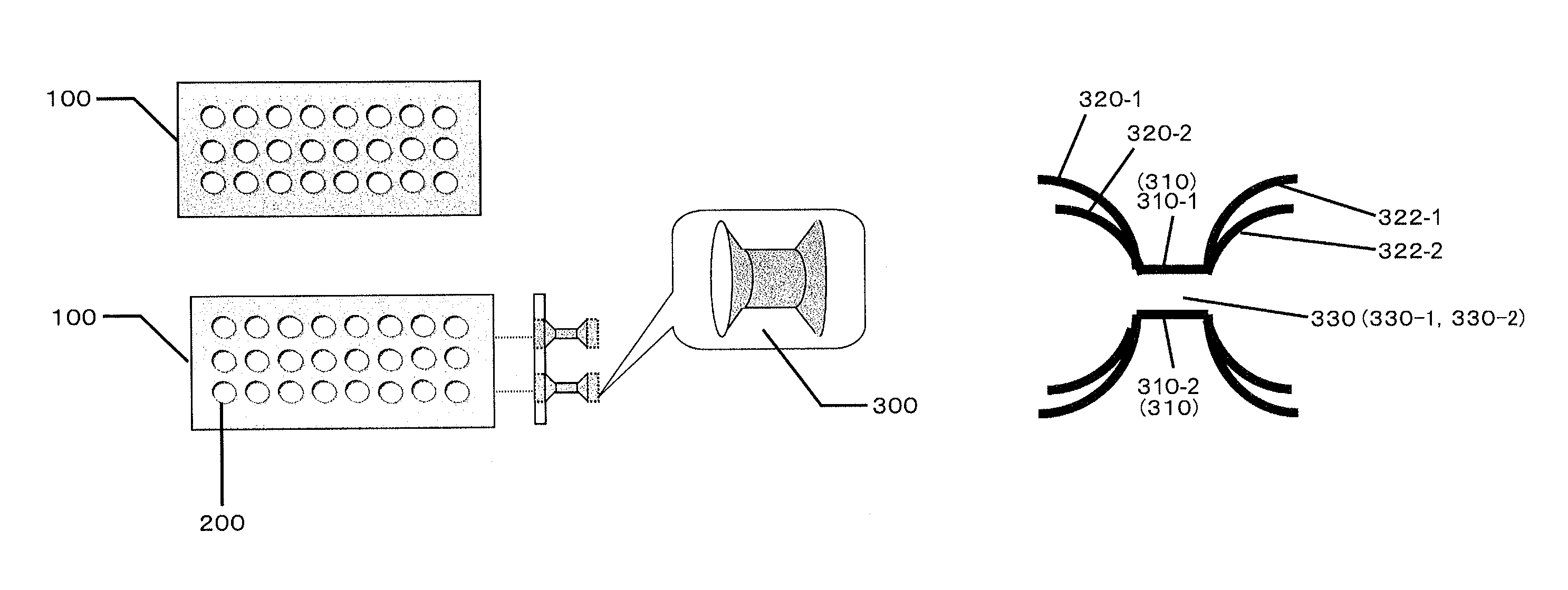
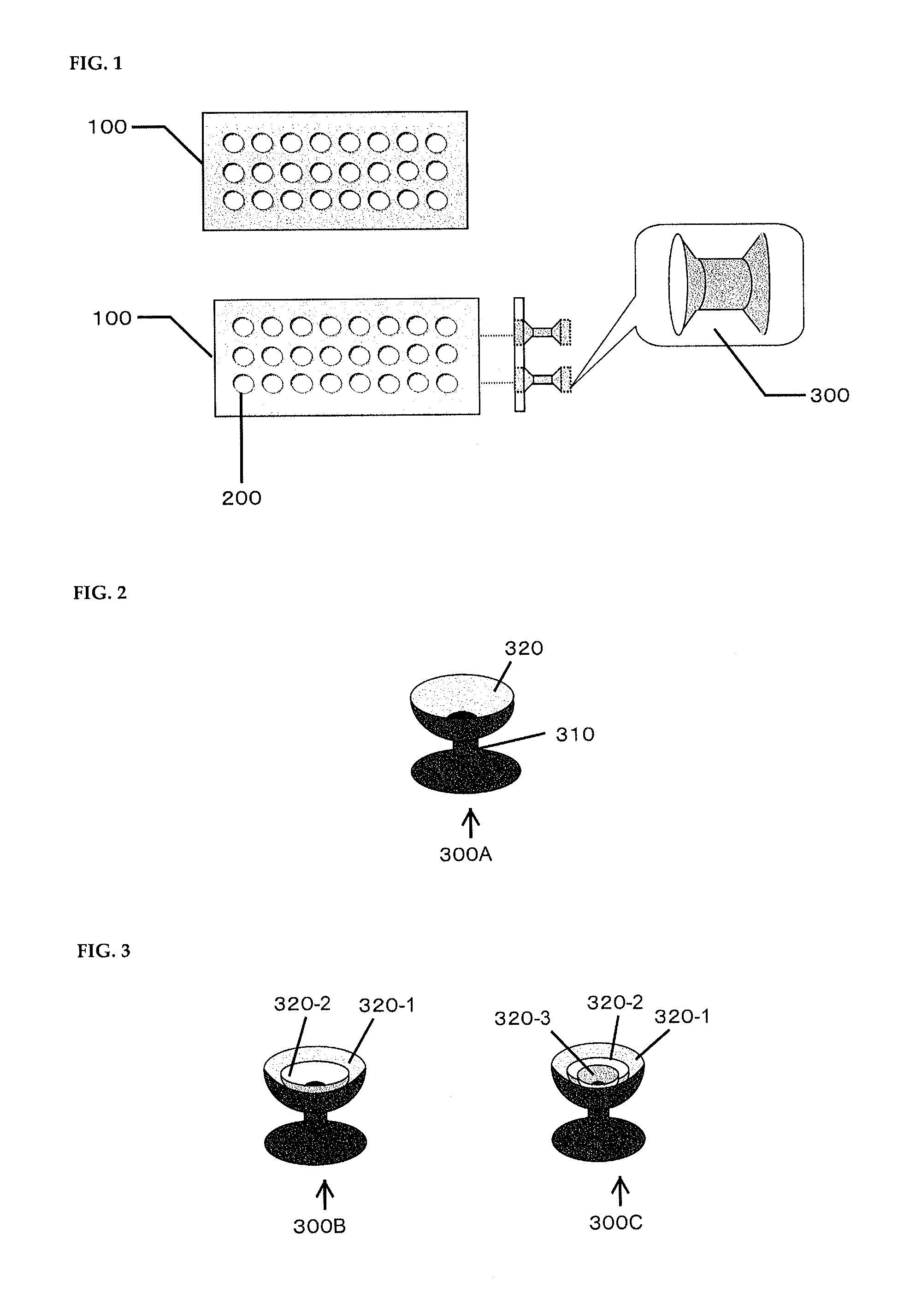
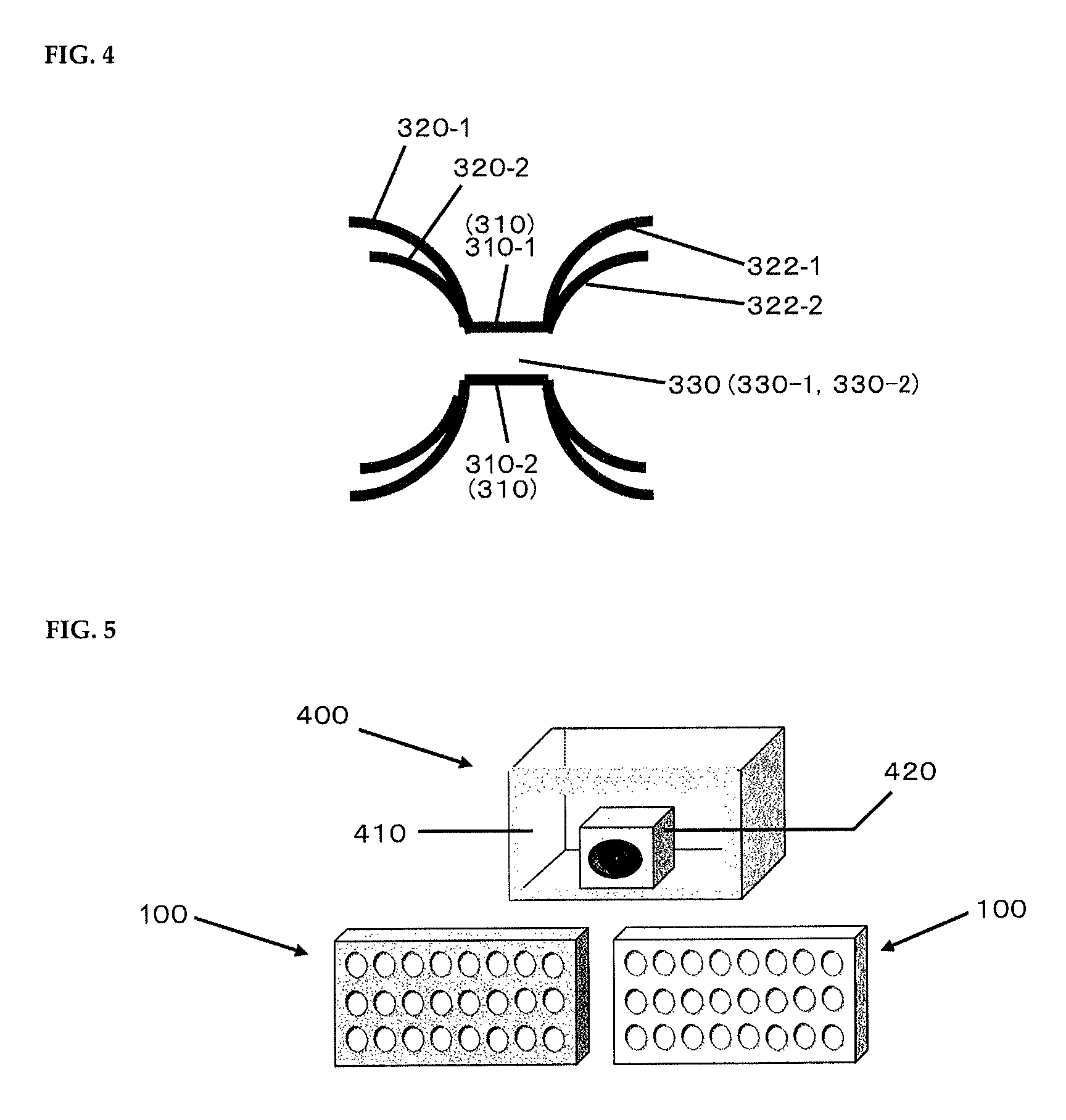
[0045]FIG. 1 is a schematic view showing a substrate 100 which is a constituting element of a soundproofing plate. The substrate 100 has 24 through holes 200 arranged in three rows. To describe the respective dimensions for reference, the dimensions of the substrate 100 in the lateral direction in the drawing is 300 to 450 mm, the diameter of the through holes 200 is 15 to 40 mm, and the pitch between the holes is about 30 to 180 mm. The through holes 200, as per their names, are apertures penetrating th...


PUM


Abstract

A soundproofing plate comprising a substrate having a substrate having at least one through hole formed therein; and a soundproofing device mounted on the through hole of the substrate. The soundproofing device has a multiplex structure having at least a first structure and a second structure nested therein. The first structure comprises a through hole (“first air passage hole”) disposed in the center and communicating with the through hole of the substrate, and a first sound collecting portion disposed at both ends or one end and having a larger size than the aperture area of the first air passage hole, and being arranged so as to reflect incident noise. The second structure comprises a through hole (“second air passage hole”) disposed in the center and communicating with the through hole of the substrate, and a second sound collecting portion disposed at both ends or one end and having a larger size than the aperture area of the second air passage hole, and being arranged so as to reflect incident noise.

Description

TECHNICAL FIELD[0001]The present invention relates to a soundproofing plate for effectively reducing transmitted acoustic energy while permitting the flow of air, and a soundproofing device mounted on such a soundproofing plate.BACKGROUND ART[0002]A general method of shielding against noise from indoors or outdoors is by shutting it out with walls, doors or windows. Additionally, when noise is generated within a specific area, there are methods of sealing off the relevant area. Methods for doing so include using tightly sealable sashes for doors and windows, giving them a double structure, or using sound-absorbing materials. In any case, this usually necessitates blocking the flow of air between the source of the noise and the area to be soundproofed.[0003]On the other hand, soundproofing methods allowing air flow include those such as the “soundproofed low energy consumption healthy living room system using natural circulation of outdoor air” described in JP 2003-21373 A, wherein b...

Claims


Application Information

Patent Timeline
Patent Type & Authority Patents(United States)
IPC IPC(8): E04B1/82E04B1/84E04B1/74G10K11/16
CPCG10K11/161G10K11/002
Inventor KITAMURA
Owner KITAMURA CO LTD
Learn More