
Pivot bearing with turned damper clamping

a technology of damper clamping and bearing, which is applied in the direction of resilient suspensions, suspensions, vehicle components, etc., can solve the problems of high weight, high cost of precise production of the cone in the clamping rings to ensure the optimum accommodation disadvantage of additional deformation of the spring strut, so as to achieve the effect of satisfying the strength requirements, preventing induced stress peak, and much material or weigh

Active Publication Date: 2014-04-29
GEORG FISCHER AG A SCHAFFHAUSEN (SUISSE)
View PDF8 Cites 4 Cited by
  • Summary
  • Abstract
  • Description
  • Claims
  • Application Information

AI Technical Summary

Benefits of technology

The design achieves a lighter, stronger pivot bearing that reduces material usage and production costs while preventing stress peaks and deformation under load, ensuring optimal damper clamping and stability.

Problems solved by technology

The disadvantage of such a pivot bearing is the massive construction which has a high weight due to the extensive clamping oriented against the inside of the vehicle; this is undesirable in modern vehicles since the aim is to reduce fuel consumption.
This is less massive, but precise production of the cone in the clamping rings to guarantee optimum accommodation of the spring strut is very costly to produce.
However the bolt is arranged such that it intersects the spring strut tube in a segmented manner, which entails the disadvantage of additional deformation of the spring strut.

Method used


Image

  • Pivot bearing with turned damper clamping
  • Pivot bearing with turned damper clamping
  • Pivot bearing with turned damper clamping

Examples


Embodiment Construction

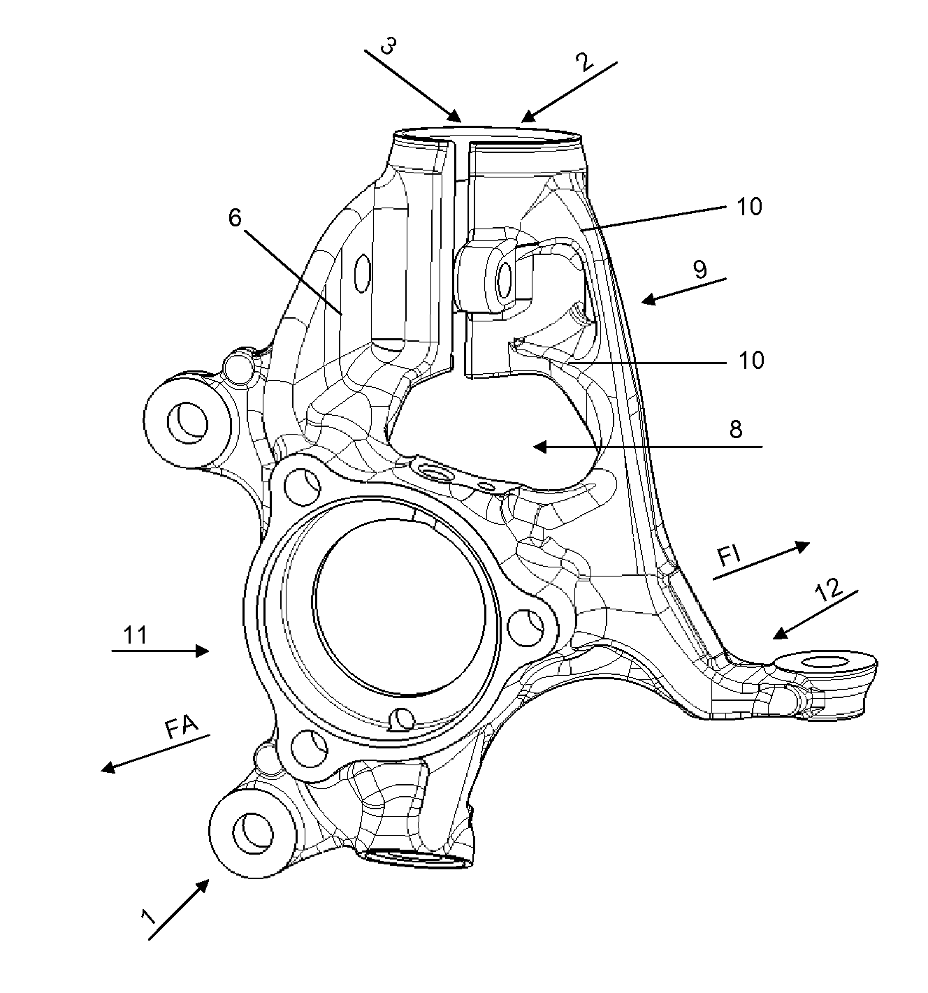
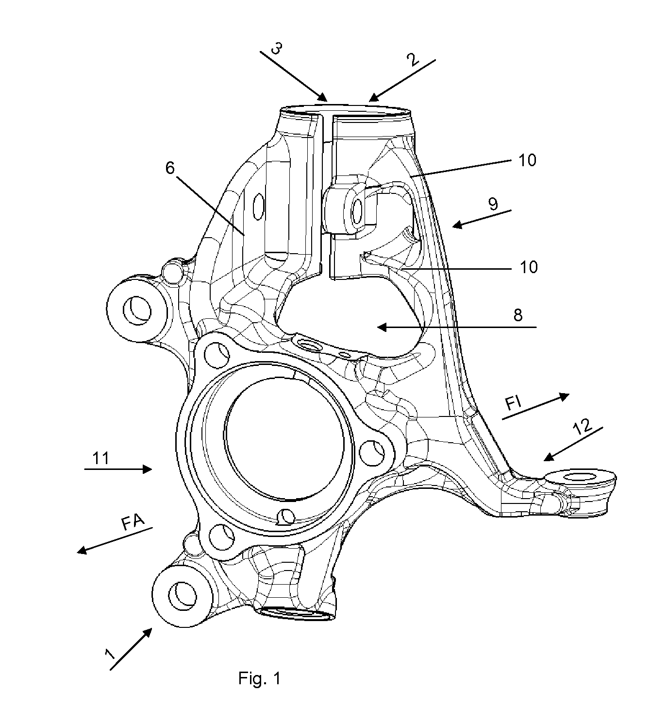
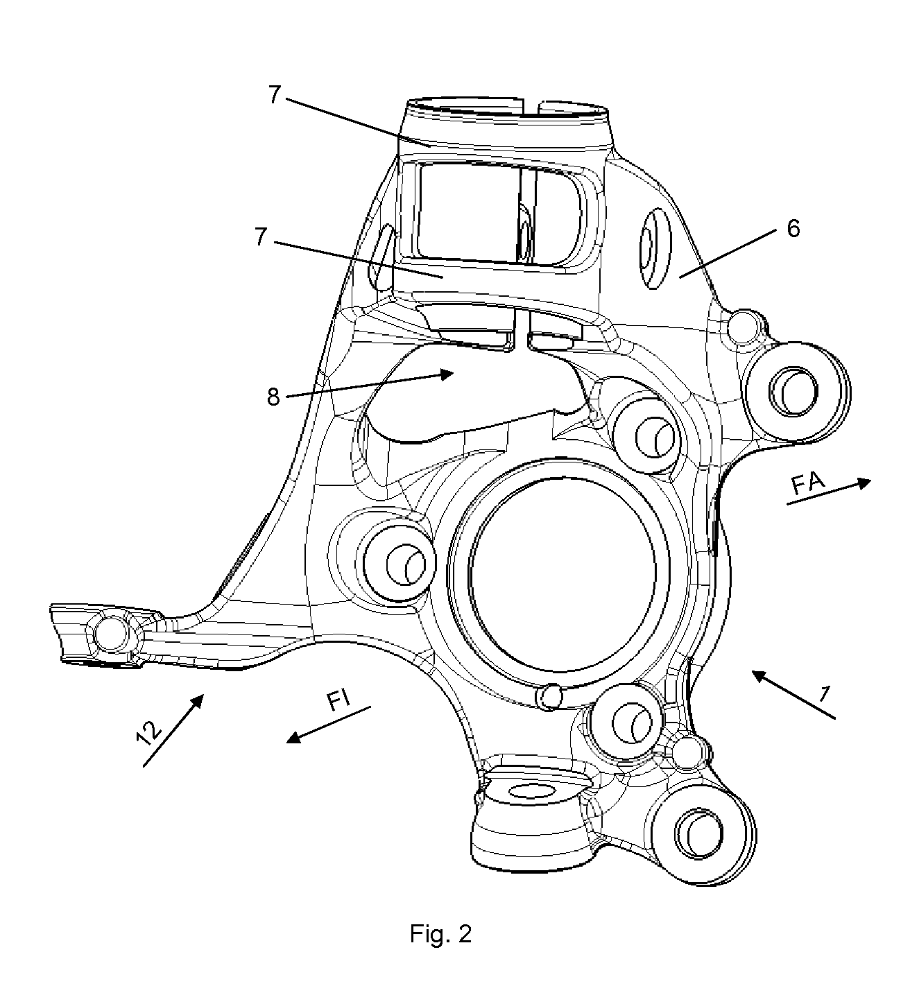
[0019]FIG. 1 shows a pivot bearing 1 according to the invention. The wheel bearing receiver 11 serves for installation of a wheel bearing (not shown). The arrow directions FA and FI shown in the drawings point respectively towards the vehicle outside FA and the vehicle inside FI when the pivot bearing 1 is in fitted state. The spring strut receiver 2 arranged on the pivot bearing 1 serves for fixing of the spring strut or shock absorber (not shown). The damper clamping 3 on the pivot bearing 1 according to the invention is arranged on the spring strut receiver 2 in the direction of the vehicle outside FA. In conventional pivot bearings, the clamping usually takes place on the vehicle inside of the pivot bearing. In order to make the pivot bearing 1 as light as possible, all unnecessary material has been omitted and existing structures are utilised repeatedly in their function. Thus the carrier rib 6 also serves as a support surface 14 for the clamping element 13. Firstly this avoids...


PUM

PropertyMeasurementUnit
ductileaaaaaaaaaa
outer diameteraaaaaaaaaa
weightaaaaaaaaaa

Abstract

Pivot bearing for a wheel suspension, in particular for a front axle of a motor vehicle, containing a wheel bearing receiver, a steering arm, a spring strut receiver with a damper clamping and a carrier rib, wherein the damper clamping of the spring strut receiver faces the vehicle outside and the pivot bearing has an opening in the region between the wheel bearing receiver and the damper clamping.

Description

BACKGROUND OF THE INVENTION[0001]The invention concerns a pivot bearing for a wheel suspension, in particular for a front axle for a motor vehicle, containing a wheel bearing receiver, a steering arm, a spring strut receiver with a damper clamping and a carrier rib.[0002]Pivot bearings constitute a connection between the damper or spring strut, the wheel bearing, the steering gear and the transverse control arm on the front axle of a motor vehicle.[0003]DE 102 12 873 B4 discloses a pivot bearing in which the spring strut is inserted with its free lower end into a clamping ring provided on the pivot bearing, which clamping ring is tightened by means of a bolt-nut connection such that the pivot bearing is held securely on the lower end of the spring strut. The disadvantage of such a pivot bearing is the massive construction which has a high weight due to the extensive clamping oriented against the inside of the vehicle; this is undesirable in modern vehicles since the aim is to reduce...

Claims


Application Information

Patent Timeline
Patent Type & Authority Patents(United States)
IPC IPC(8): B62D7/18
CPCB60G2200/142Y10T29/49647B60G2204/129B60G2206/50B60G2206/8111B62D7/18B60G15/07B60G13/006B60G2206/8101B60G2206/7102
Inventor ROHDE, THOMASHESS, STEFANMAHNIG, DOMINIK
Owner GEORG FISCHER AG A SCHAFFHAUSEN (SUISSE)
Learn More