Wiper connecting device
- Summary
- Abstract
- Description
- Claims
- Application Information
AI Technical Summary
Benefits of technology
Problems solved by technology
Method used
Image
Examples
first embodiment
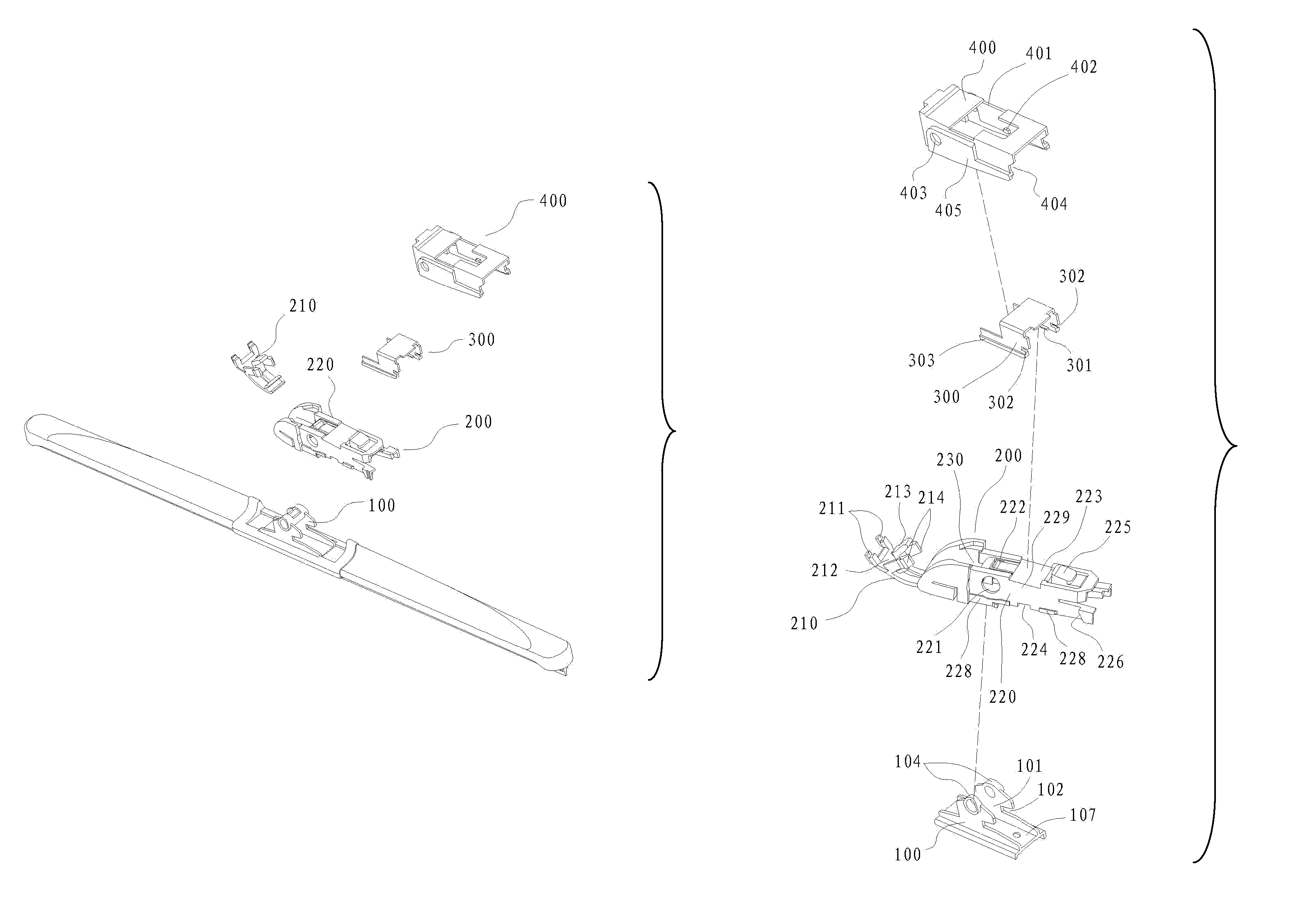
[0057]As shown in FIG.9 and FIG.10, this utility model is a matched fixation of this connecting device and the wiper arm (A10). The wiper arm (A10) is an existing structure. The connecting device of the utility model is a combination of base (100), connector (200), stop pad (300) and functional external cap (400), and through the external-cap through hole (403) of combined joint and the base circular-pipe (104), matches with the round pin (A11). The both side faces (405), along with the big opening (401), form a lower concave surface, which matches with the curve-shaped pressing plate (A12) of wiper arm (A10) to achieve an installation and use of wiper arm (A10).
second embodiment
[0058]As shown in FIG. 11 and FIG. 12, this is this utility model and wiper arm. After the functional external cap (400) of combined joint is removed, a combination of base (100), connector (200) and stop pad (300) remain. An installation and usage of wiper arm (A20) is achieved through a matching of the limiting flanged lips on both sides of n-shaped stop pad (300) with the inner side wall (A21) of wiper arm (A20) and inward bending face (A24), and through pressing the front edge (A22) tightly with two bulge pressing blocks (211) of movable cap (210) at the front end of connector (200), and through a matching of the stuck boss (225) on top face of the back end of connector (200) with the wiper arm hole (A23) in order to limit the slipping out.
third embodiment
[0059]As shown in FIG. 13 and FIG. 14, this is this utility model and wiper arm about connection. After the n-shaped stop pad (300) of composite unit is removed, and through a matching of segmented lateral margins-flanged lips (228) on both side faces of connector (200) and notches (102) on side faces of base with the inner side wall (A31) of wiper arm (A30) and the inward bending face (A33), and through pressing the front edge (A32) at top face of wiper arm with two bulge pressing blocks (211) of movable cap at the front end of connector (200), and through a matching of the stuck boss (225) at the back end of main body (200) with the wiper-arm hole (A33) in order to limit the limiting out, and through the position-limiting notch (102) of base (100) to limit the angle of rotation, an installation and usage of wiper arm (A30) is achieved.
PUM
 Abstract
Description
Claims
Application Information
 - R&D
- Intellectual Property
- Life Sciences
- Materials
- Tech Scout
- Unparalleled Data Quality
- Higher Quality Content
- 60% Fewer Hallucinations
Browse by: Latest US Patents, China's latest patents, Technical Efficacy Thesaurus, Application Domain, Technology Topic, Popular Technical Reports.
© 2025 PatSnap. All rights reserved.Legal|Privacy policy|Modern Slavery Act Transparency Statement|Sitemap|About US| Contact US: help@patsnap.com


