
A spreader acting on the f-rail

A spreader and hanger technology, which is applied in the field of spreaders acting on F rails, and can solve the problems of easy damage to the flatness of the rail row surface, etc.

Active Publication Date: 2017-01-11
CHINA RAILWAY 11TH BUREAU GRP +1
View PDF8 Cites 0 Cited by
  • Summary
  • Abstract
  • Description
  • Claims
  • Application Information

AI Technical Summary

Problems solved by technology

[0007] In view of this, the object of the present invention is to provide a spreader acting on the F rail, which can effectively solve the problem that the spreader is easy to damage the flatness of the rail row surface

Method used


Image

  • A spreader acting on the f-rail
  • A spreader acting on the f-rail
  • A spreader acting on the f-rail

Examples


Embodiment Construction

[0029] The embodiment of the present invention discloses to provide a sling acting on the F rail, which can effectively solve the problem that the sling easily damages the flatness of the rail row surface.

[0030] The following will clearly and completely describe the technical solutions in the embodiments of the present invention with reference to the accompanying drawings in the embodiments of the present invention. Obviously, the described embodiments are only some, not all, embodiments of the present invention. Based on the embodiments of the present invention, all other embodiments obtained by persons of ordinary skill in the art without making creative efforts belong to the protection scope of the present invention.

[0031] see Figure 2-Figure 5 , figure 2 Schematic diagram of the structure of the hanger provided by the embodiment of the present invention; image 3 for figure 2 Schematic diagram of the front view structure of the spreader in ; Figure 4 for fi...


PUM


Abstract

The invention discloses a lifting appliance acting on rails F. The lifting appliance comprises a lifting frame and a plurality of supporting devices. Each supporting device comprises a rotary shaft and a horizontally-arranged supporting plate, the rotary shafts and lifting frame are rotatably connected, and rotary axes are vertically arranged. One end of each supporting plate is used for providing supporting force for the rail handle portions of the rails F, the other ends of the supporting plates are fixedly connected with the rotary shafts, at least one supporting device is arranged along a first straight line, at least one supporting device is arranged along a second straight line, and the first straight line is parallel to the second straight line. Due to the fact that the large supporting faces of the supporting plates are used for providing supporting force for a rail row, the damage degree of the surface of the rail row can be lowered; meanwhile, due to the rotatable design of the supporting plates, the supporting plates can stretch into the lower sides of the rail handle portions for supporting the rail handle portions, and supporting force can be provided for the two rails F at the same time. The supporting plates support the rails F of the rail row, and the problem that the distance between sleepers is uncertain can be effectively solved.

Description

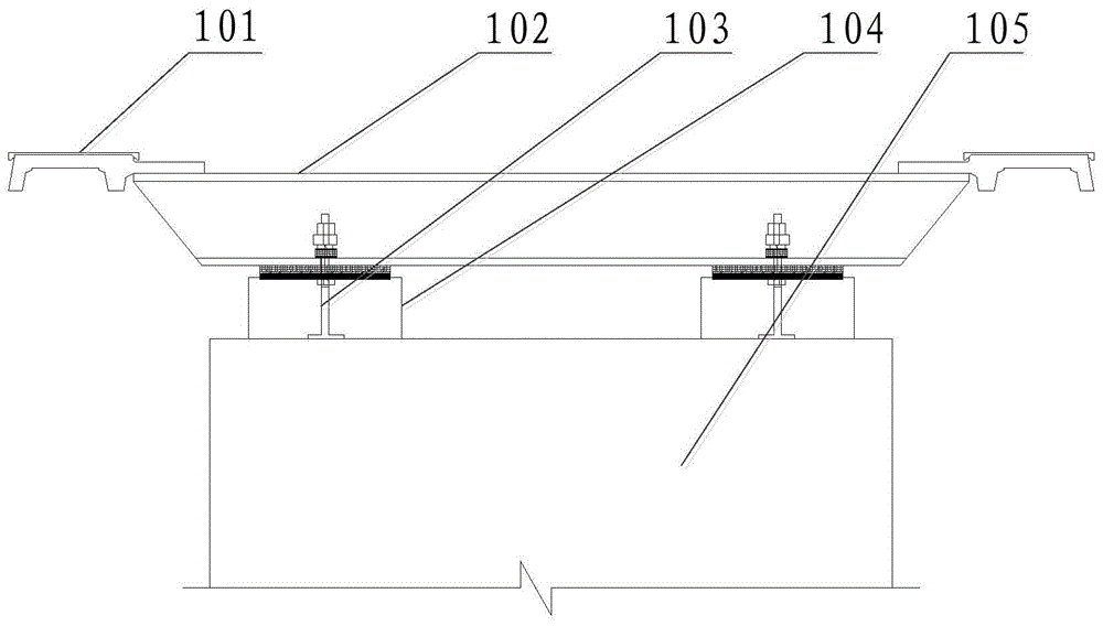
technical field [0001] The invention relates to the technical field of hoisting machinery, more specifically, to a hoisting tool acting on an F rail. Background technique [0002] The laying of the track of the maglev train generally involves sequentially connecting the rail rows that have been fully assembled before leaving the factory, and then laying the entire track. [0003] figure 1 It is a structural schematic diagram of a cross-section of a common rail row laid in the prior art. The rail row is generally composed of two F rails 101 arranged parallel to each other and a plurality of sleepers 102 arranged perpendicular to the F rails 101. The two ends of the sleepers 102 along the extension direction are fixedly connected with the F rails 101 respectively. I-shaped. The F rail 101 includes a rail shank and a rail groove. The rail shank is plate-shaped, that is, the cross-section is rectangular; while the cross-section of the rail groove is concave, and the bottom of...

Claims


Application Information

Patent Timeline
Patent Type & Authority Patents(China)
IPC IPC(8): E01B29/16
Inventor 张军林刘育鸿唐希峰雷鹏飞柯尊鸿巴东良柯露徐王进
Owner CHINA RAILWAY 11TH BUREAU GRP
Learn More