Timepiece bearing, movement, and portable timepiece

a timepiece bearing and movement technology, applied in the direction of frequency stabilisation mechanism, instruments, etc., can solve the problems of deteriorating suppress torque fluctuation, and improve the time indication accuracy of the timepiece.

Inactive Publication Date: 2014-04-22
SEIKO INSTR INC
View PDF15 Cites 15 Cited by
  • Summary
  • Abstract
  • Description
  • Claims
  • Application Information

AI Technical Summary

Benefits of technology

[0012]Due to this construction, it is possible to rotate the shaft member around the axis, with no space formed between the shaft member and the bearing member. Thus, even if the attitude of the timepiece bearing is changed or an impact is applied thereto, it is possible to suppress fluctuation in the position of the shaft member. As a result, it is possible to suppress fluctuation in torque, so that it is possible to achieve an improvement in terms of the time indication accuracy of the timepiece.
[0057]In the timepiece bearing of the present invention, it is possible to rotate the shaft member around the axis with no space formed between the shaft member and the bearing member, so that, even if the attitude of the timepiece bearing is changed or an impact is applied thereto, it is possible to suppress fluctuation in the position of the shaft member. As a result, it is possible to suppress fluctuation in torque, so that it is possible to achieve an improvement in term of the time indication accuracy of the timepiece.

Problems solved by technology

As a result, the time indication accuracy of the timepiece deteriorates.

Method used


Image

  • Timepiece bearing, movement, and portable timepiece
  • Timepiece bearing, movement, and portable timepiece
  • Timepiece bearing, movement, and portable timepiece

Examples


Embodiment Construction

[0079]Next, a timepiece bearing according to an embodiment of the present invention will be described with reference to FIGS. 1 through 20. In this embodiment, described below, the timepiece bearing is applied to a portable mechanical timepiece such as a wristwatch.

(Mechanical Timepiece)

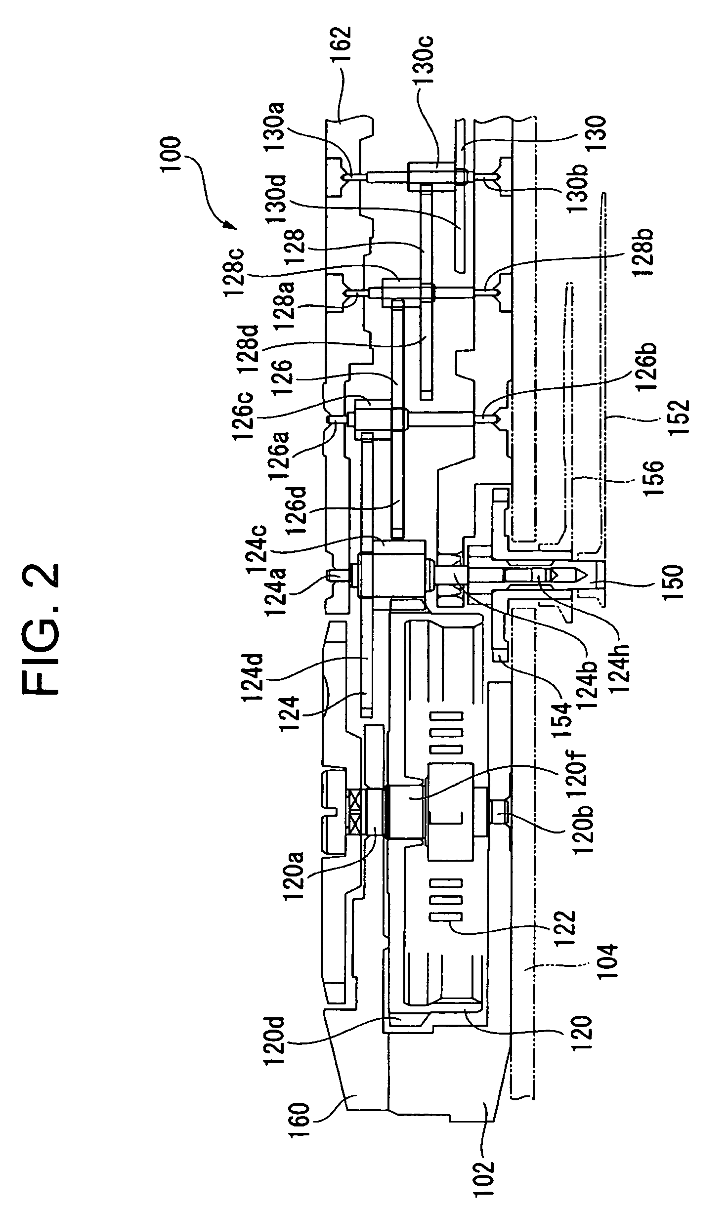
[0080]As shown in FIGS. 1 through 3, a movement 100 of a mechanical timepiece has a main plate 102 constituting a base plate of the movement 100. A winding stem 110 is rotatably incorporated into a winding stem guide hole 102a of the main plate 102. A dial 104 (See FIG. 2) is mounted to the movement 100. Generally speaking, of the two sides of the main plate 102, the side where the dial 104 is arranged is referred to as the back side of the movement 100, and the side opposite to the side where the dial 104 is arranged is referred to as the front side of the movement 100. A train wheel assembled to the front side of the movement 100 is referred to as the front train wheel, and a train wheel assembled ...


PUM


Abstract

A timepiece bearing has a bearing member of unitary construction that is provided at least at one end portion of a shaft member for undergoing rotation around an axis and that regulates movement of the shaft member in axial and radial directions of the shaft member. An elastic member applies an urging force in an axial direction of the bearing member to hold the bearing member in contact with the shaft member. A frame member supported by and fixed to a support member contains the bearing member. The elastic member is provided so as to establish connection between the bearing member and the frame member. The shaft member is configured to undergo rotation around the rotational axis while the shaft member and the bearing member are held in contact with each other by the elastic member.

Description

BACKGROUND OF THE INVENTION[0001]1. Field of the Invention[0002]The present invention relates to a timepiece bearing, a movement, and a portable timepiece.[0003]2. Description of the Related Art[0004]Conventionally, a rotating mechanical component such as a gear used in a portable timepiece, such as a wristwatch or a pocket watch, is formed such that a bearing is arranged so as to contain rotation shaft ends thereof and that the rotation shaft is rotated while guided by the bearing to transmit torque, thereby ticking away the time.[0005]Here, as the construction of a conventional timepiece bearing, a construction as shown in FIG. 21 is known (See, for example, JP-A-2004-294320). FIG. 21 is a sectional view of a balance with hairspring.[0006]As shown in FIG. 21, a balance with hairspring 520 includes a balance staff 523 whose thin small-diameter portions 521 and 522 at both ends thereof are supported so as to be rotatable around a center axis C by a timepiece bearing 510 formed in a ...

Claims


Application Information

Patent Timeline
Patent Type & Authority Patents(United States)
IPC IPC(8): G04B31/00
CPCG04B17/06G04B31/02G04B31/0082G04B31/012
Inventor HIRAOKA, MASASHINAKAJIMA, MASAHIRONIWA, TAKASHI
Owner SEIKO INSTR INC
Why Eureka
Try Eureka