
Environment property estimaton and graphical display

a technology of environmental properties and graphical displays, applied in the field of environmental property estimation and graphical displays, can solve the problems of difficult to develop a practical system based on current commercially available surgical robots, lack of haptic feedback, and difficulty in finding the location of calcified arteries in heart tissue,

Active Publication Date: 2014-04-15
THE JOHN HOPKINS UNIV SCHOOL OF MEDICINE
View PDF11 Cites 141 Cited by
  • Summary
  • Abstract
  • Description
  • Claims
  • Application Information

AI Technical Summary

Problems solved by technology

However, the lack of haptic feedback has been recognized as one of the drawbacks of such teleoperated robot-assisted minimally invasive surgery (RMIS) systems (F. W. Mohr, V. Falk, A. Diegeler, T. Walther, J. F. Gummert, J. Bucerius, S. Jacobs, and R. Autschbach, “Computer-enhanced ‘robotic’ cardiac surgery: experience in 148 patients,”The Journal of Thoracic and Cardiovascular Surgery, vol.
459-470, 2007, and M. Tavakoli, R. Patel, M. Moallem, and A. Aziminejad, Haptics for Teleoperated Surgical Robotic Systems (New Frontiers in Robotics series), World Scientific Publishing Company, 2008, have studied teleoperation with haptic feedback for surgical applications, the trade-off between stability and transparency, and force sensor issues such as cost, biocompatibility, and sterilizability, make it difficult to develop a practical system (based on current commercially available surgical robots) with realistic haptic feedback (A. M. Okamura, L. N. Verner, C. E. Reiley, and M. Mahvash, “Haptics for robot-assisted minimally invasive surgery,” in Proceedings of the International Symposium Robotics Research, Hiroshima, Japan, Nov. 26-29, 2007) and (A. M. Okamura, “Haptic feedback in robot-assisted minimally invasive surgery,” Current Opinion in Urology, vol.
Without force feedback, finding the location of a calcified artery in heart tissue is quite challenging, and surgeons may be unable to determine the best location for anastomosis (F. W. Mohr, V. Falk, A. Diegeler, T. Walther, J. F. Gummert, J. Bucerius, S. Jacobs, and R. Autschbach, “Computer-enhanced ‘robotic’ cardiac surgery: experience in 148 patients,”The Journal of Thoracic and Cardiovascular Surgery, vol.

Method used


Image

  • Environment property estimaton and graphical display
  • Environment property estimaton and graphical display
  • Environment property estimaton and graphical display

Examples


examples

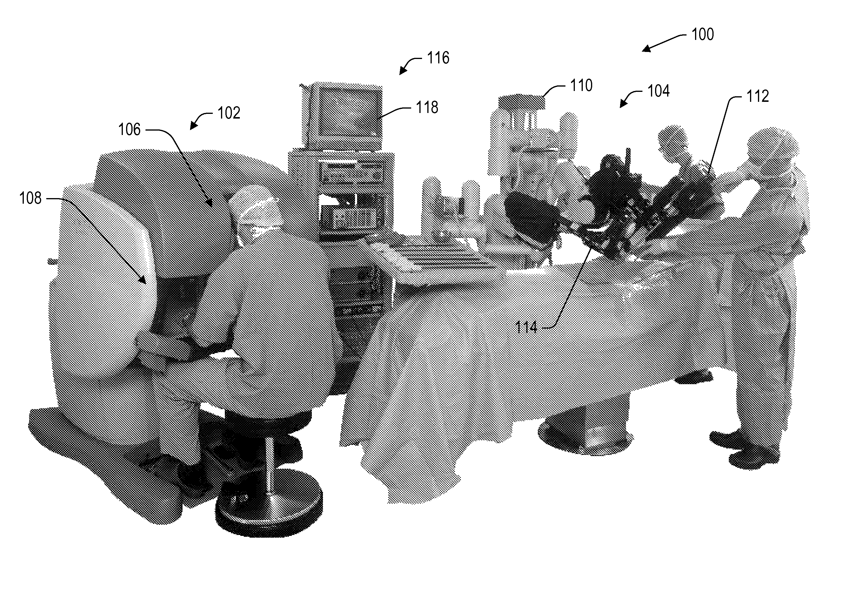
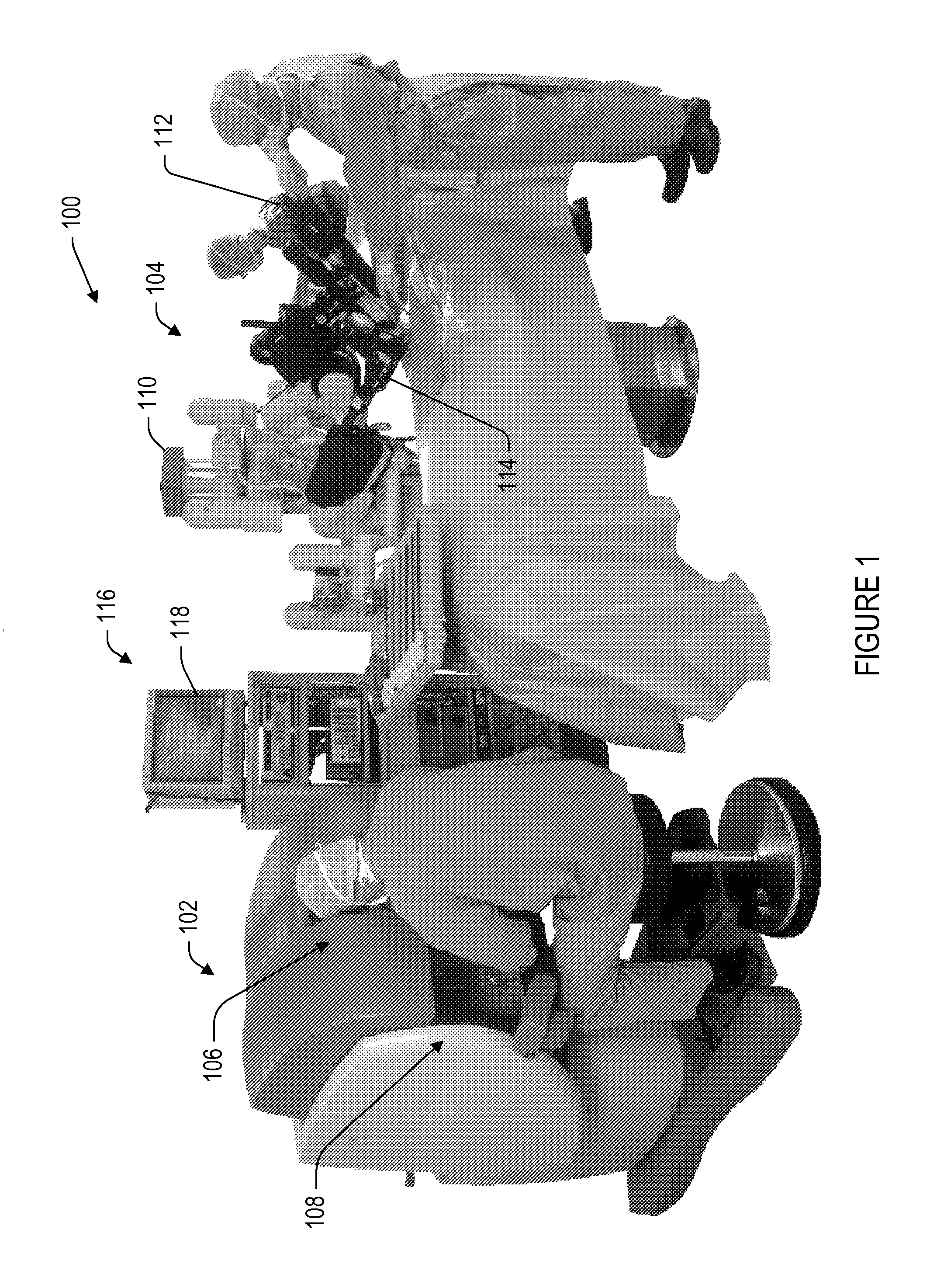
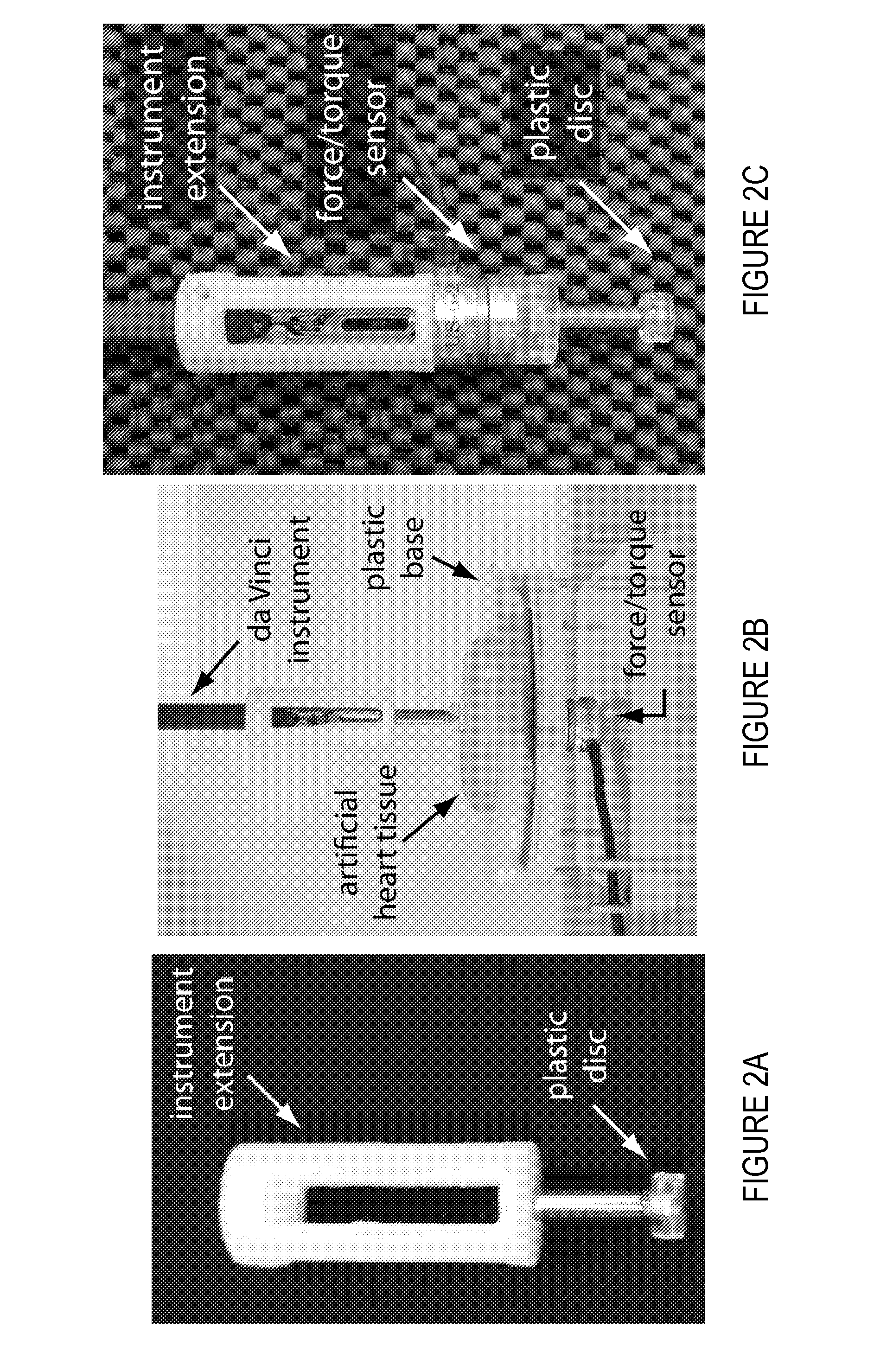
[0043]Manual palpation of tissue and organs during a surgical procedure provides clinicians with valuable information for diagnosis and surgical planning. In present-day robot assisted minimally invasive surgery systems, lack of perceptible haptic feedback makes it challenging to detect a tumor in an organ or a calcified artery in heart tissue. This example presents an automated tissue property estimation method and a real-time graphical overlay that allow an operator to discriminate hard and soft tissues. We first evaluate experimentally the properties of an artificial tissue and compare seven possible mathematical tissue models. Self-validation as well as cross-validation confirm that the Hunt-Crossley model best describes the experimentally observed artificial tissue properties and is suitable for our purpose. Second, we present the development of a system in which the artificial tissue is palpated using a teleoperated surgical robot, and the stiffness of the Hunt-Crossly model i...


PUM


Abstract

A surgical robot including an imaging system comprising at least one camera, a processor in communication with the imaging system, a manipulation system in communication with the processor, and a visual display in communication with the processor. The processor is operable to calculate a stiffness estimate for an area of an environment based on an environment model of tool-environment interaction data, create a composite image comprising a stiffness map of the stiffness estimate overlaid on an environment image from the at least one camera, and output the composite image on the visual display.

Description

CROSS-REFERENCE TO RELATED APPLICATION[0001]This application claims priority to U.S. Provisional Application No. 61 / 106,683 filed Oct. 20, 2008, the entire contents of which are hereby incorporated by reference, and is a U.S. national stage application under 35 U.S.C. §371 of PCT / US2009 / 061297, filed Oct. 20, 2009, the entire contents of which are incorporated herein by reference.[0002]The U.S. Government has a paid-up license in this invention and the right in limited circumstances to require the patent owner to license others on reasonable terms as provided for by the terms of Grant Nos. IIS-0347464, EEC-9731748 and CNS-0722943, awarded by the National Science Foundation, and of Grant No. R01-EB002004, awarded by the National Institutes of Health.BACKGROUND[0003]1. Field of Invention[0004]The current invention relates to environment property estimation and graphical display, and more particularly to a surgical robot operable to graphically display environment property estimates.[0...

Claims


Application Information

Patent Timeline
Patent Type & Authority Patents(United States)
IPC IPC(8): A61B5/00
CPCA61B19/50G05B2219/37065A61B19/5225A61B2019/465A61B19/46A61B2019/464B25J9/1671A61B19/2203G05B19/4207A61B2019/5227G05B2219/37357A61B2019/501G05B2219/45117G05B2219/35506A61B19/5212A61B34/30A61B90/37A61B2034/101A61B2090/064A61B34/10A61B90/06A61B90/361A61B2090/065A61B2090/371G06F3/14
Inventor OKAMURA, ALLISON MARIKOYAMAMOTO, TOMONORIVAGVOLGYI, PETER BALAZS
Owner THE JOHN HOPKINS UNIV SCHOOL OF MEDICINE
Learn More