Control method for reducing the audio noise

a control method and audio noise technology, applied in climate sustainability, power conversion systems, instruments, etc., can solve the problems of not being able to fundamentally solve the audio noise problem, audio noise is caused, and audio noise is especially apparent, so as to reduce the audio noise of the power source coverer and reduce the effect of audio nois

Active Publication Date: 2014-04-15
DELTA ELECTRONICS INC
View PDF16 Cites 0 Cited by
  • Summary
  • Abstract
  • Description
  • Claims
  • Application Information

AI Technical Summary

Benefits of technology

[0009]An aspect of the present disclosure provides a control method for reducing the audio noise. In the control method, an input power source, a power source converter and a load are provided. The input power source includes a first terminal and a second terminal. The power source converter includes a first input terminal, a second input terminal, a first output terminal, a second output terminal, an output capacitor and a component having a mechanical resonant frequency. The first input terminal of the power source converter is connected to the first terminal of the input power source. The second input terminal of the power source converter is connected to the second terminal of the input power source. The first terminal of the output capacitor is connected to the first output terminal of the power source converter, and the second terminal of the output capacitor is connected to the second output terminal of the power source converter. The component having the mechanical resonant frequency is coupled to one of the first input terminal, the second input terminal, the first output terminal and the second output terminal of the power source converter. The load includes a first terminal and a second terminal. The first terminal of the load is connected to the first terminal of the output capacitor, and the second terminal of the load is connected to the second terminal of the output capacitor. The power source converter is set to operate in a discontinuous operation (or burst) mode which has a burst cycle. The burst cycle includes an operating period Tburst<sub2>—< / sub2>on and an idle period Tburst<sub2>—< / sub2>off, and the operating period Tburst<sub2>—< / sub2>on of the burst cycle includes at least one single pulse period Ts. The electrical energy transferred from the first input terminal and the second input terminal to the first output terminal and the second output terminal of the power source converter in the operating period Tburst<sub2>—< / sub2>on is controlled, so as to reduce the audio noise of the power source coverer.

Problems solved by technology

However, traditional magnetic components (such as inductors and transformers) of a power source converter in the BM mode are often affected by variable magnetic fields with frequency equal to that of the BM mode, and thus audio noise is caused.
Once the frequency is close to the mechanical resonant frequency of the magnetic components, resonance case happens to the magnetic components, and at this time, the audio noise is especially apparent.
One technical solution is adopted to change the mechanical structure and the installation manner of the magnetic components, such as bonding, securing, increasing of sound propagation distance and adding of a sound-proof housing, but these manners cannot fundamentally solve the audio noise problem.
However, these methods for reducing the amplitude of the magnetic field are often relatively mechanical and are not beneficial to optimize the efficiency of light load or non-load state.
In order to solve the above disadvantages existing in the conventional techniques, the related industries have been endeavored to seek for a solution, but an appropriate manner is not found for such a long time.

Method used


Image

  • Control method for reducing the audio noise
  • Control method for reducing the audio noise
  • Control method for reducing the audio noise

Examples


first embodiment

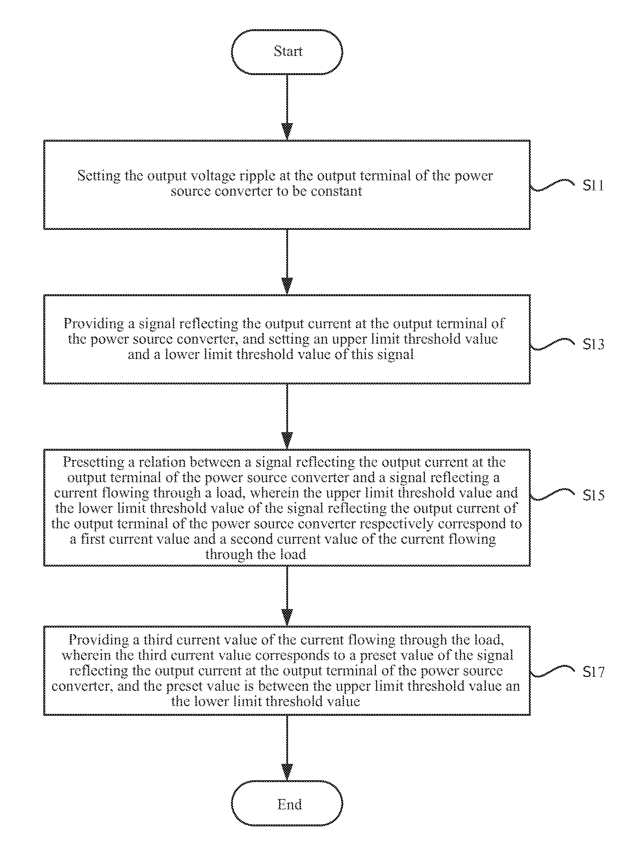
[0046]FIG. 6 illustrates a flow chart of the control method of the present disclosure. Referring to FIG. 6, in this control method, firstly in step S11, the output voltage ripple at the output terminal of the power source converter is set to be constant; next in step S13, a signal reflecting the output current at the output terminal of the power source converter is provided, and an upper limit threshold value and a lower limit threshold value of this signal are set; and subsequently in step S15, a relation between the signal reflecting the output current at the output terminal of the power source converter and the signal reflecting a load current is preset, and the upper limit threshold value and the lower limit threshold value of the signal reflecting the output current of the output terminal of the power source converter respectively correspond to a first current value and a second current value of the load current; finally in step S17, a third current value of the load current is...

second embodiment

[0048]FIG. 7 illustrates a flow chart of the control method of the present disclosure. Referring to FIG. 7, in the control method, firstly in step S21, the output current at the output terminal of the power source converter is set to be constant; next in step S23, the output voltage ripple at the output terminal of the power source converter is provided, and an upper limit threshold value and a lower limit threshold value of the output voltage ripple are set; and subsequently in step S25, the relation between the output voltage ripple at the output terminal of the power source converter and a signal reflecting a load current is preset, and the output voltage ripples at the output terminal of the power source converter respectively correspond to a first current value and a second current value of the load current; finally in step S27, a third current value of the load current is provided, which corresponds to a preset value of the output voltage ripple at the output terminal of the p...

third embodiment

[0051]FIG. 8 illustrates a flow chart of the control method of the present disclosure. Referring to FIG. 8, in the control method, firstly in step S31, the output voltage ripple at the output terminal of the power source converter is set to be constant; next in step S33, an upper limit threshold value and a lower limit threshold value of a signal reflecting the output current at the output terminal of the power source converter are set; and subsequently in step S35, a reference frequency Fburst—ref is provided, and the actual burst frequency of the power source converter is compared with the reference frequency to obtain the error therebetween; and finally in step S37, the output current at the output terminal of the power source converter is regulated by utilizing the error so as to reduce the audio noise of the power source converter.

[0052]In an embodiment, if the actual burst frequency is greater than or equal to the reference frequency, the control method includes the step of de...


PUM


Abstract

A control method for reducing audio noise is disclosed. The method includes the steps of: providing an input power source; providing a power source converter having a component with a mechanical resonant frequency, coupled to the input terminal or the output terminal of the power source converter; providing an output capacitor and a load connected in parallel therebetween; making the power source converter operate in a burst mode; and controlling the electrical energy transferred from the input terminal to the output terminal of the power source converter during an operating period of every burst cycle, so as to reduce the audio noise of the power source converter.

Description

CROSS-REFERENCE TO RELATED APPLICATIONS[0001]This application claims priority to Chinese Application Serial Number 201210196396.2, filed Jun. 4, 2012, which is herein incorporated by reference in its entirety.BACKGROUND OF THE INVENTION[0002]1. Field of Invention[0003]The present disclosure relates to power electronics technology. More particularly, the present disclosure relates to a control method for reducing audio noises.[0004]2. Description of Related Art[0005]Currently, as a power supply conversion device of an electronic product, a power source converter is widely applied to various fields including military industry, scientific research, industrial control, communication, electric power, LED illumination, instruments and apparatuses. Along with the continuous improvement of the power source converter, the operating efficiency of the power source converter in light load and no-load output situation is increasingly valued.[0006]Generally, in order to improve the efficiency, wh...

Claims


Application Information

Patent Timeline
Patent Type & Authority Patents(United States)
IPC IPC(8): G05F3/02
CPCH02M1/44H02M2001/0035H02M1/15Y02B70/16Y02B70/10H02M1/0035
Inventor JIN, HONG-YUANDAI, JIA-LEGAN, HONG-JIANYING, JIAN-PING
Owner DELTA ELECTRONICS INC
Why Eureka
Try Eureka