Transparent thin plate

a thin plate and transparent technology, applied in the field of transparent thin plates, can solve the problems of remarkably inconvenient key operation, and achieve the effect of easy recognition, easy perception with the naked eye, and equal width

Inactive Publication Date: 2014-04-08
NISSHA PRINTING COMPANY
View PDF21 Cites 2 Cited by
  • Summary
  • Abstract
  • Description
  • Claims
  • Application Information

AI Technical Summary

Benefits of technology

[0019]According to the present invention, the mesh layer has a light transmittance of 50% or more, and is a layer wherein the outline of meshes is made of the bands, which are very thin and have a substantially equal width; therefore, the outline is not easily perceived as a whole so that the whole is perceived to be transparent. On the other hand, the mesh layer area having, on the surface thereof, the colored layer has a nature that the pattern of the colored layer is easily recognized through the boundary between the area where the colored layer is formed and the area where the colored layer is not formed. Accordingly, when the transparent thin plate is viewed from the side on which the colored layer is arranged, the pattern can be perceived by the effect of the colored layer. On the other hand, when the transparent thin plate is viewed from the side on which the colored layer is not arranged, the mesh layer cannot be perceived so that the thin plate is perceived to be transparent as a whole.
[0020]When the band width of the mesh layer is set to 30 μm or less, the mesh layer is not easily perceived with the naked eye. Thus, the transparency of the transparent thin plate can be made high.
[0021]When the low reflection layer is arranged on the surface of the mesh layer or the colored layer, reflection on the mesh layer is restrained so that the layer can be made difficult to perceive.

Problems solved by technology

However, in the state that the flip cover is opened, a pattern for showing an inputting position is not given at all, so that the key operation becomes remarkably inconvenient.

Method used


Image

  • Transparent thin plate
  • Transparent thin plate
  • Transparent thin plate

Examples


Embodiment Construction

[0041]With reference to the drawings, a transparent thin plate according to an embodiment of the present invention will be described hereinafter.

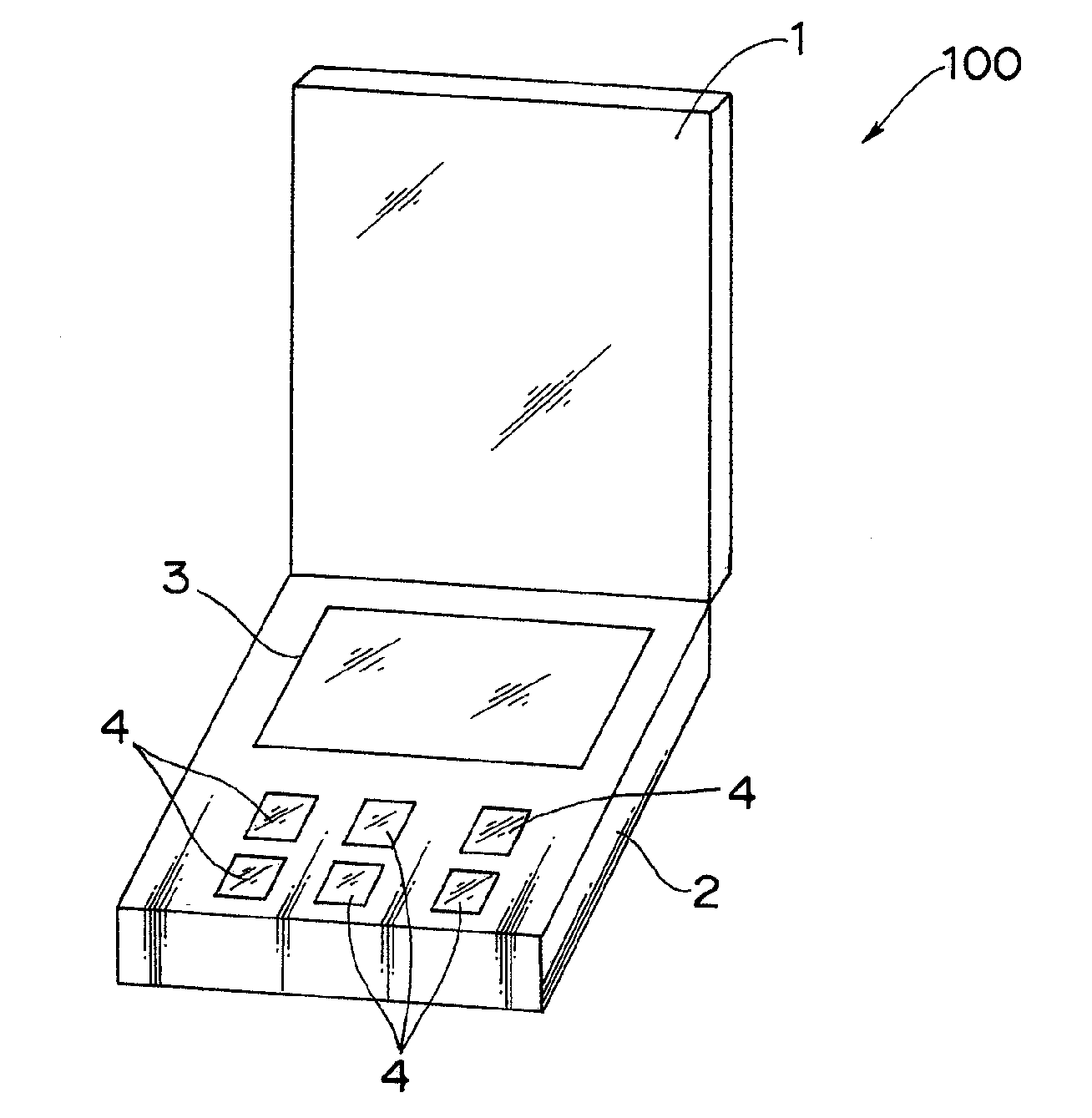
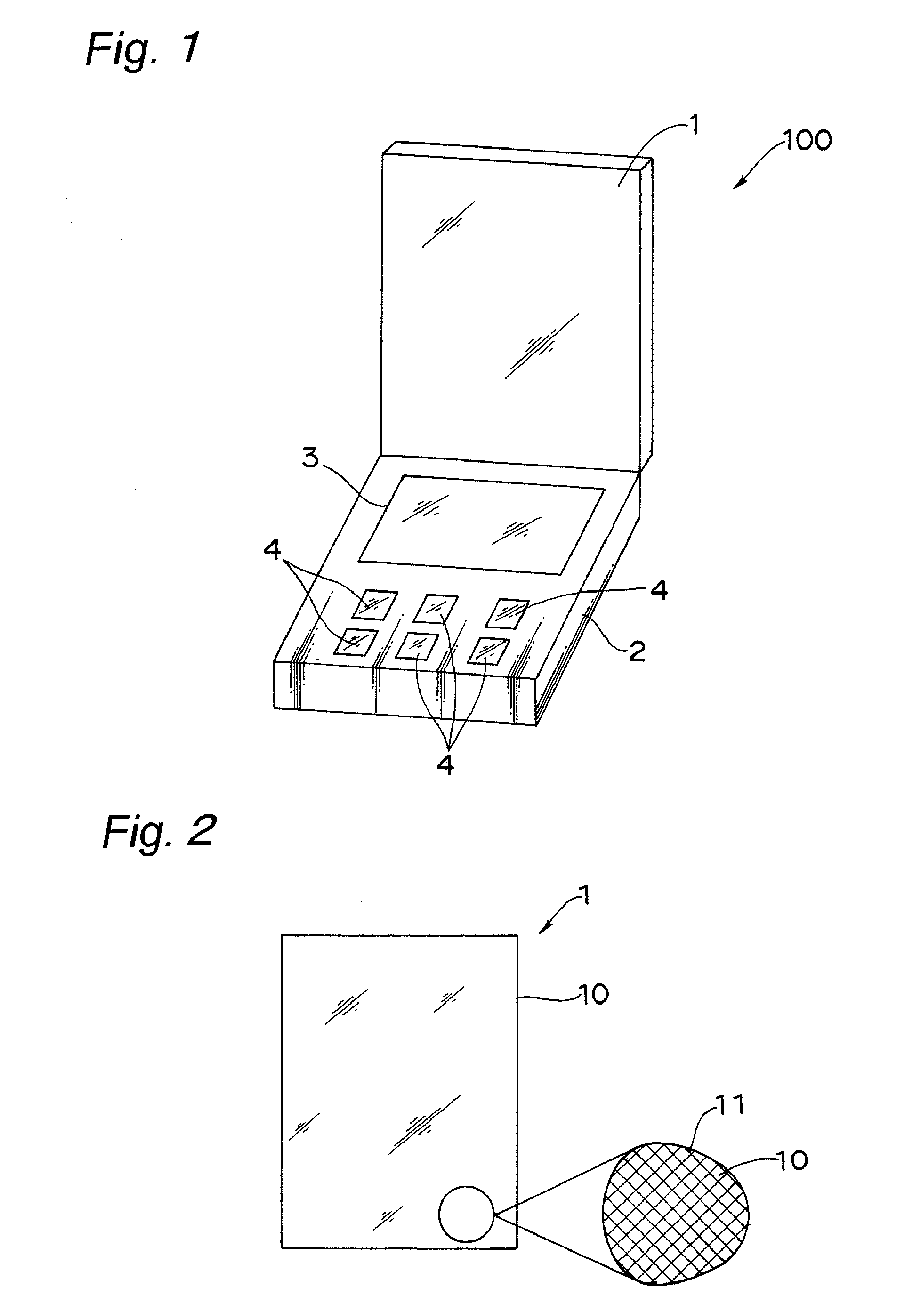
[0042]FIG. 1 is a schematic view illustrating an external structure of a portable instrument terminal wherein the transparent thin plate according to an embodiment of the present invention is used as a flip cover. A portable instrument terminal 100, which is the terminal, is provided with a body 2 having a display 3 and operating buttons 4, and a flip cover 1. The flip cover is bonded to the body 2 with hinges in such a manner that the cover can be opened from the body 2 and closed toward the body 2. In the state where the cover is closed, the cover functions as a cover for protecting the display 3 and the operating buttons 4 in the body surface. Furthermore, in the state that the cover is opened, the cover is positioned over the body as illustrated in FIG. 1, and functions as an antenna and / or an electrostatic capacity switch by aid of an ...


PUM

PropertyMeasurementUnit
band widthaaaaaaaaaa
light transmittanceaaaaaaaaaa

Abstract

A transparent thin plate including a transparent substrate in a sheet form, a mesh layer formed on a surface of the transparent substrate and made of an opaque material having a structure wherein an outline of meshes is made of bands that are very thin and have a substantially equal width, and having a light transmittance of 50% or more. The transparent thin plate also includes a colored layer that is arranged in a state in which the colored layer is laminated in a partial area of the mesh layer and on the surface of the mesh layer, and has a color different from that of the opaque material constituting the mesh layer.

Description

BACKGROUND OF THE INVENTION[0001]1. Technical Field[0002]The present invention relates to a transparent thin plate wherein a mesh layer made of meshes having a fine structure is formed on a surface of a transparent substrate. More specifically, the present invention relates to a transparent thin plate that is preferably usable for a transparent flip cover usable in an electrostatic capacity switch electrode, an antenna or others that are used in portable instruments, household electric appliances, automobile equipment, or the like.[0003]2. Description of the Related Art[0004]About portable instruments, household electric appliances, PDAs, automobile equipment, and other small-sized instruments, there is known a type wherein a transparent flip cover is set up to an instrument and the instrument is used in the state that the flip cover is opened during use. In connection with the function of this flip cover, the cover is used merely to protect the body of the instrument in many cases;...

Claims


Application Information

Patent Timeline
Patent Type & Authority Patents(United States)
IPC IPC(8): H05K1/00H05K1/09
CPCG06F1/1656G06F3/044G06F1/1626H01Q1/243G06F2203/04112G06F2203/04103B23B5/02H01B5/14
Inventor OKUMURA, SHUZOOMOTE, RYOMEIHASHIMOTO, TAKAOMATSUI, YUKI
Owner NISSHA PRINTING COMPANY
Why Eureka
Try Eureka