
Dual-loop control for laser annealing of semiconductor wafers

a laser annealing and dual-loop technology, applied in the direction of manufacturing tools, after-treatment details, crystal growth process, etc., can solve the problems of limiting the temperature uniformity performance of laser annealing, temperature measurement error, temperature control system instability, etc., to reduce the noise of 1/f and reduce the variation in the annealing temperature

Inactive Publication Date: 2014-04-08
VEECO INSTR
View PDF11 Cites 17 Cited by
  • Summary
  • Abstract
  • Description
  • Claims
  • Application Information

AI Technical Summary

Benefits of technology

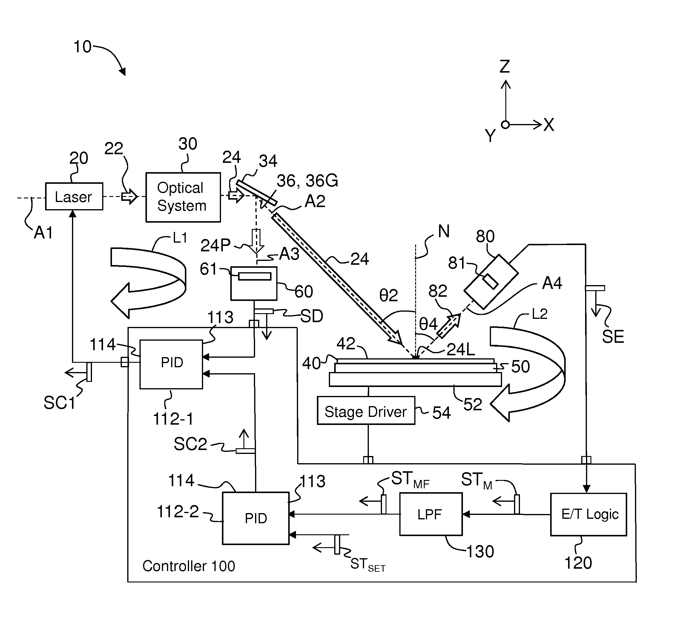
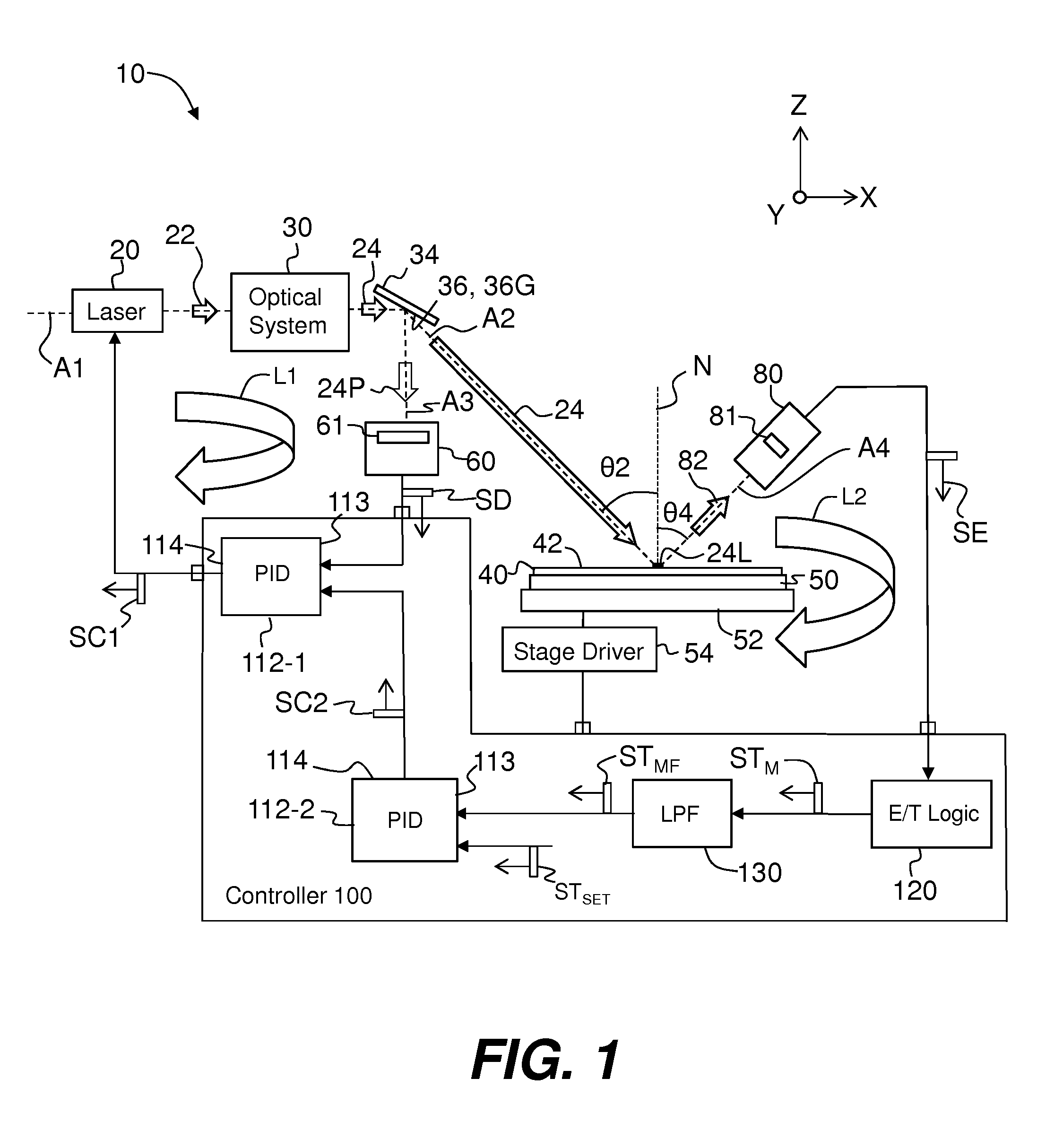
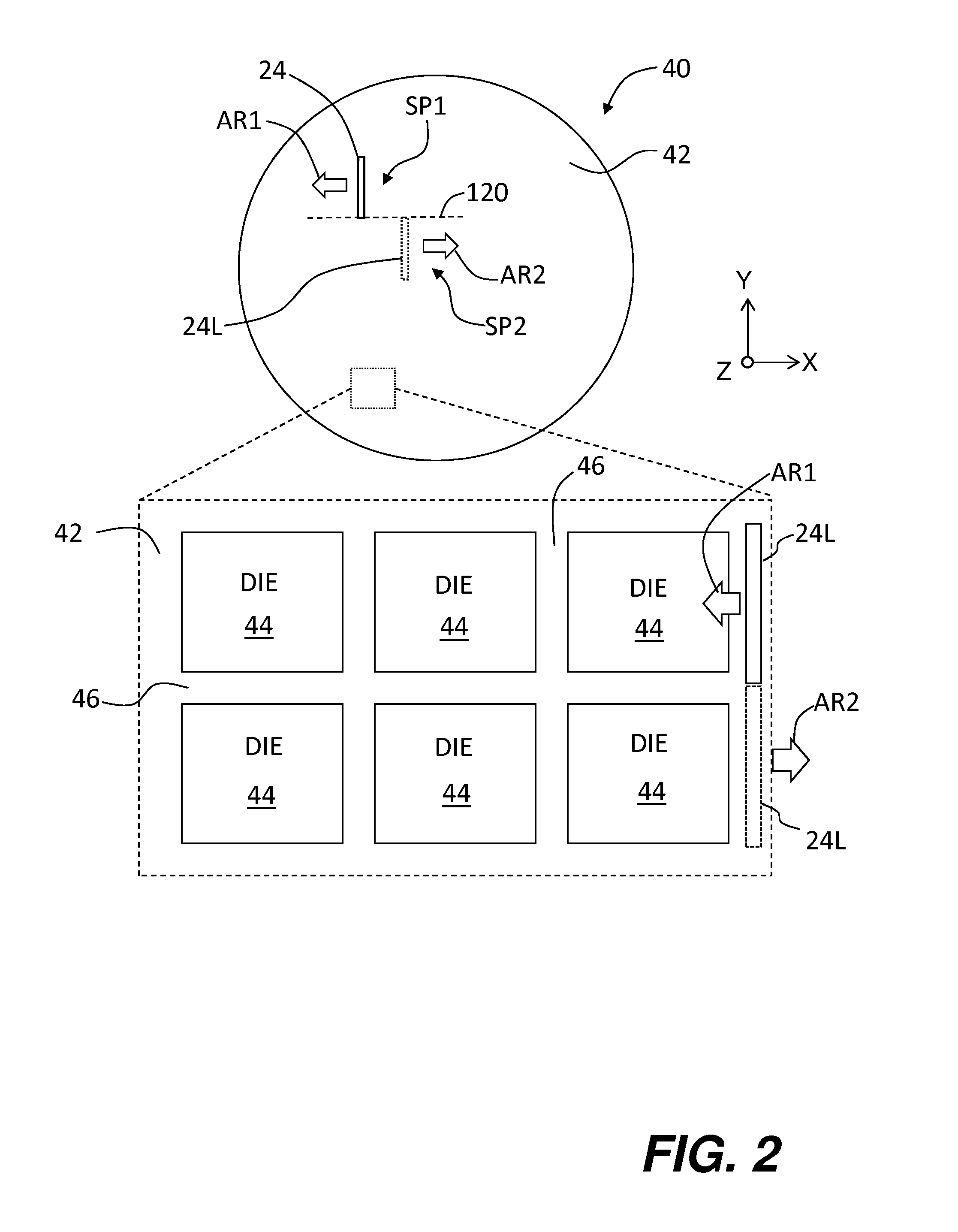
This patent describes a system for annealing semiconductor wafers with different devices on them. It uses a laser to create a small focused beam of light which is directed onto the surface of the wafer while it moves. This beam quickly reaches its maximum intensity and then slowly decreases back down to room level. During this process, the laser's output power can be adjusted to minimize any unwanted fluctuations (called 1/f noise) that may affect the quality of the final product. A special camera detects how well the laser is doing its job and sends signals to the computer controlling the laser to make changes if needed. By measuring these changes, researchers hope they will better understand what factors are important when trying to optimize the performance of individual devices on the wafer during the annealing process.

Problems solved by technology

The technical problem addressed in this patent relates to maintaining constant and stable annealing temperatures during semiconductor manufacturing processes despite significant variations in emissivity levels caused by different patterns on various device wafers. Open-loop processing limitations make it difficult to compensate for these variations through adjustments to laser power density and substrate temperature, resulting in lower overall anneal temperature performances while still keeping the extreme values safely below damaging thresholds.

Method used


Image

  • Dual-loop control for laser annealing of semiconductor wafers
  • Dual-loop control for laser annealing of semiconductor wafers
  • Dual-loop control for laser annealing of semiconductor wafers

Examples


Embodiment Construction

[0018]Reference is now made in detail to embodiments of the disclosure, examples of which are illustrated in the accompanying drawings. Whenever possible, the same or like reference numbers and symbols are used throughout the drawings to refer to the same or like parts.

[0019]FIG. 1 is a schematic diagram of an example laser annealing system 10 that illustrates an embodiment of the dual-loop control configuration for the system. A Cartesian coordinate system is shown for the sake of reference. Example laser annealing systems 10 are described, for example, U.S. Pat. Nos. 7,612,372, 7,154,066 and 6,747,245, and U.S. Patent Application Publications No. 2010 / 0084744 and 2012 / 0100640, all of which are incorporated by reference herein.

[0020]System 10 includes laser 20 that emits an initial laser beam 22 along an optical axis A1 that runs in the X-direction. An example laser 20 is a CO2 laser that emits light at a nominal annealing wavelength λA of 10.6 μm. Laser 20 may also consist of or i...


PUM

PropertyMeasurementUnit
Temperatureaaaaaaaaaa
Angleaaaaaaaaaa

Abstract

Systems and methods for performing semiconductor laser annealing using dual loop control are disclosed. The first control loop operates at a first frequency and controls the output of the laser and controls the 1/f laser noise. The second control loop also controls the amount of output power in the laser and operates at second frequency lower than the first frequency. The second control loop measures the thermal emission of the wafer over an area the size of one or more die so that within-die emissivity variations are average out when determining the measured annealing temperature. The measured annealing temperature and an annealing temperature set point are used to generate the control signal for the second control loop.

Description


Claims


Application Information

Patent Timeline
Owner VEECO INSTR
Learn More