Insert for a breast pump

a breast pump and insert technology, applied in the field of inserts for breast pumps, can solve the problems of inefficiency, discomfort or difficulty of users, and the inability to adjust the insert to the preference of mothers, so as to prevent friction discomfort, facilitate deformation, and facilitate the effect of predictability

Active Publication Date: 2014-04-01
KONINK PHILIPS ELECTRONICS NV
View PDF14 Cites 21 Cited by
  • Summary
  • Abstract
  • Description
  • Claims
  • Application Information

AI Technical Summary

Benefits of technology

[0065]The progressive deformation of each resiliently deformable membrane wall 28,29 due to the varying thickness of each wall 28,29 as the pressure in the pressure chamber increases causes the primary insert 22 to impart a peristaltic action on a user's teat which promotes the expression of milk from a user's teat and is more analogous to an infant or baby compared with a conventional breast pump action. Furthermore, an advantage of the present invention is that the primary insert 22 is anatomically similar and has a similar shape and movement as a baby's tongue, and the inner part 44 of the secondary insert 40 is analogous to a baby's palate. Therefore, the natural feel of the breast pump is enhanced. Milk is expressed from the user's breast and is expelled from the funnel 10 through the passageway defined by the outer shell 13 of the funnel 10 into the main body of the breast pump and into the milk receiving vessel.
[0066]As the insert is a bladder with a lower and upper membrane wall 28,29, the insert does not need to be fixedly mounted to the funnel at its outer end to fixedly locate the insert and / or to form a pressure chamber between insert and the outer shell of the funnel in which a positive pressure can be generated to inflate the bladder. An advantage of the pressure chamber 26 being formed by the bladder 23 is that it prevents the insert from being mounted to the funnel 10 in an incorrect manner and so causing leakage and loss of function. Furthermore, in a conventional breast pump the deformation of the insert is hampered by attachment of the insert to an outer rim of the funnel. However, in the present arrangement, the insert is not constrained thereby. Additionally, this also allows predictability of deformation as material folds are not required to allow deformation at the front end of the insert.
[0067]As the resiliently deformable lower and upper membrane walls 28,29 are urged to distend outwardly, the front end 33 of the bladder 23 is urged to distend inwardly towards the inner end 14 of the funnel 10. Therefore, the front end 33 of the bladder 23 and corresponding portion of the upper membrane wall 29 is urged to slide relative to the user's breast disposed in the teat receiving space 11. However, the user's breast is located against the secondary insert 40, which extends over the front end 33 of the bladder 23 and so said front end 33 does not contact the user's breast and friction discomfort is prevented. Furthermore, as the bladder 23 is not fixedly mounted to the outer shell 13 of the funnel, the bladder 23 is not constrained and so is free to inflate without being restrained at the front end 33 of the bladder.
[0068]An advantage of the front end 33 of the bladder 23 not be constrained is that it aids the progressive deformation of the resiliently deformable membrane walls 28,29 by not restricting said deformation at the front end 33 of the bladder 23 and so said front end 33 can inflate prior to the deformation of the rest of the resiliently deformable membrane walls 28,29 to impart an improved peristaltic action on a user's teat which promotes the expression of milk from a user's teat and is more analogous to that of an infant or baby.
[0069]To cause the resiliently deformable wall 26 to distend inwardly into its original position away from a user's teat, the pressure in the teat receiving space 11 is reduced to reduce the pressure differential. Therefore, the resiliently deformable membrane 23 is urged to distend inwardly into its original position, away from the teat, due to the stiffness and resilient nature of the bladder. As the pressure differential is reduced, the thicker portion of each resiliently deformable membrane wall 28,29 returns to its original shape and position, prior to the thinner portion of each resiliently deformable membrane wall 28,29 returning to its original shape and position.
[0070]By cyclically generating a positive pressure difference between the pressure chamber 26 and the teat receiving space 11, a repeated peristaltic action is imparted on a user's teat disposed in the teat receiving space 11.

Problems solved by technology

Therefore, the adjustability of the breast pump to the preference of the mother is limited.
However, a problem with the breast pump described above is that users are known to suffer from discomfort or difficulty when using such a breast pump.
Conventional breast pumps do not produce this peristaltic motion, and so the absence of such an action means that extracting milk can be uncomfortable and inefficient.
However, disadvantages of the above breast pump arrangement include the breast pump having a complicated construction and it is difficult to achieve a satisfactory peristaltic motion which is analogous to the action of a suckling infant.

Method used


Image

  • Insert for a breast pump
  • Insert for a breast pump
  • Insert for a breast pump

Examples


Embodiment Construction

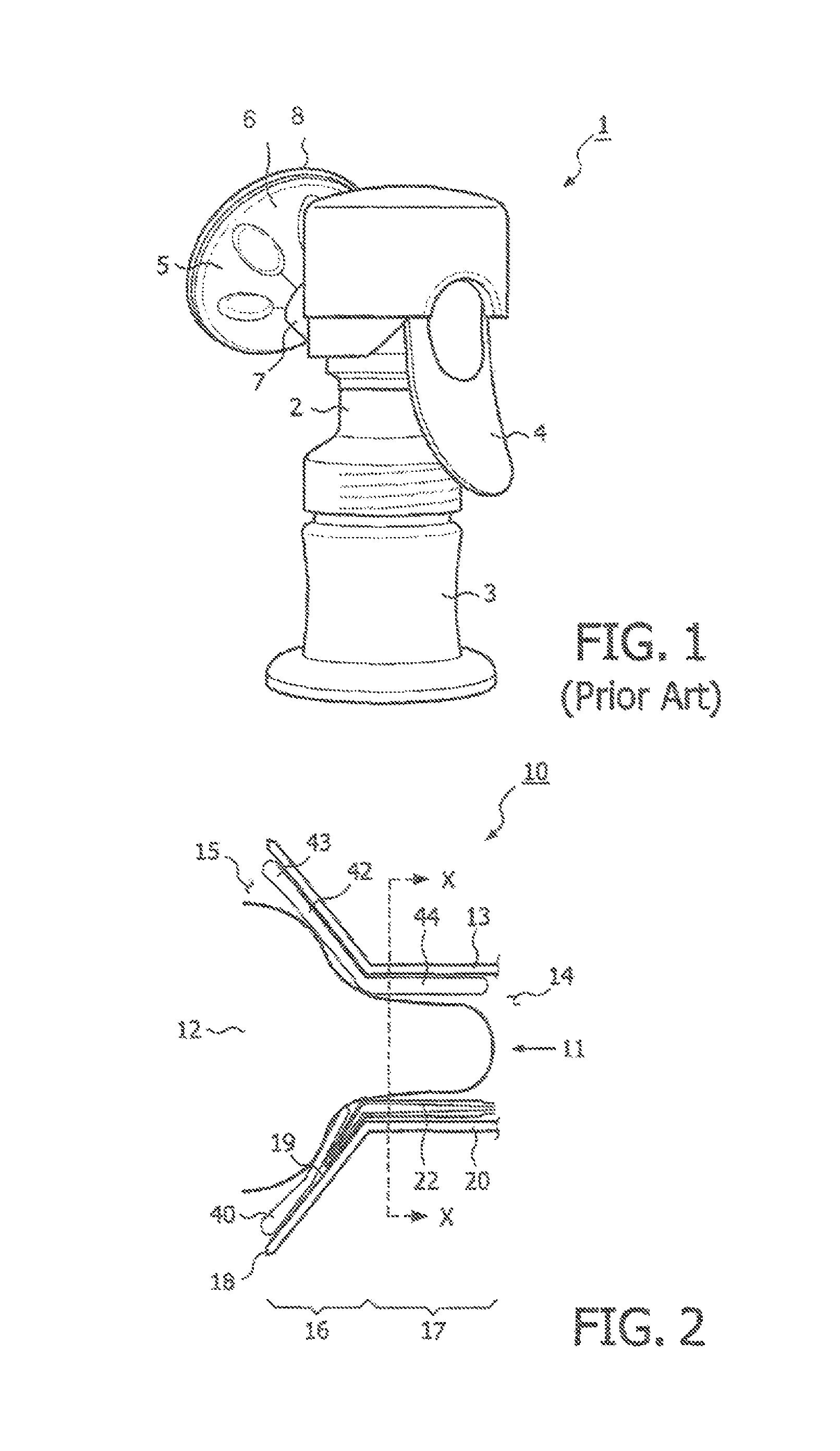
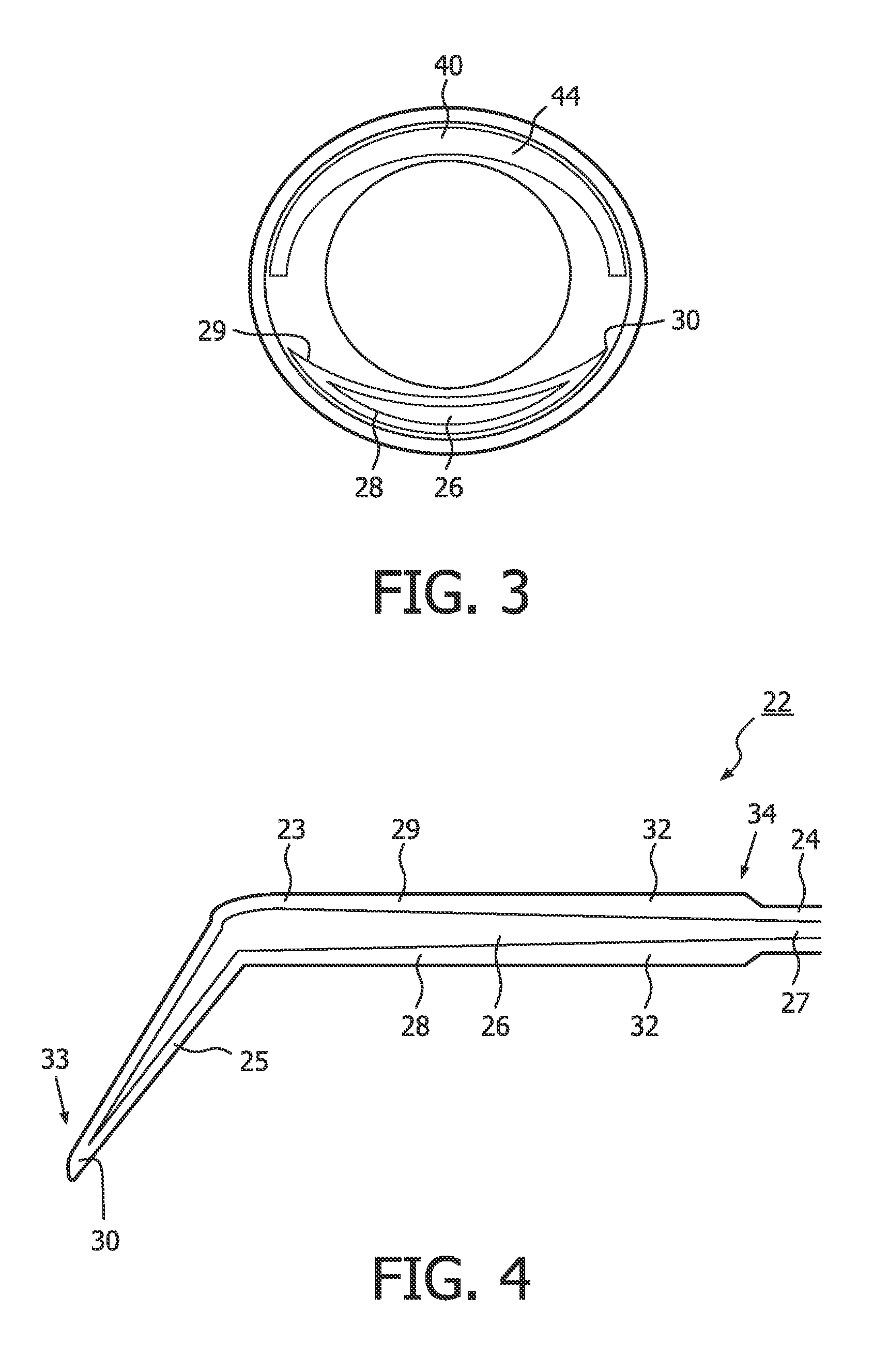
[0036]Referring now to FIGS. 2 and 3, a breast receiving funnel 10 for a breast pump unit is shown. The breast pump unit (not shown) comprises a main body and a milk-receiving vessel. The milk receiving vessel, which may take the form of a feeding bottle for an infant or baby, is attached to the main body by a screw fitting, although it will be understood that alternative releasable attachment means may be used, such as clips (not shown).

[0037]A vacuum pump unit (not shown) is disposed in the main body, to create a vacuum, as will be described hereinafter and a handle (not shown) extends from the main body. The vacuum pump unit is motorised and the handle operates a motorised vacuum pump unit (not shown) which is powered by batteries disposed in the main body. Alternatively, the handle is manually operable to operate the vacuum pump unit. The vacuum pump unit is conventional and so no further description of the pump unit will be given here.

[0038]The breast receiving funnel 10 extend...


PUM


Abstract

An insert for a breast-receiving funnel of a breast pump includes an elongate inflatable bladder which defines a pressure chamber. The elongate inflatable bladder is configured to fit in a teat receiving space of the breast receiving funnel so that the bladder extends from an inner end of the funnel towards an outer end of the funnel. The bladder lies between a user's teat and the funnel when a breast is inserted in the funnel, such that the elongate inflatable bladder is configured to deform towards a user's teat located in the teat receiving space in a predetermined manner when a pressure difference is applied between the teat receiving space and the pressure chamber such that a peristaltic action is applied to the user's teat, to aid the expression of milk therefrom.

Description

FIELD OF THE INVENTION[0001]The present invention relates to an insert for a breast pump. In particular, the present invention relates to an insert adapted to fit in a breast-receiving funnel of a breast pump which is operable to extract milk from a user. The present invention also relates to a breast-receiving funnel for a breast pump and a breast pump comprising a breast-receiving funnel.BACKGROUND OF THE INVENTION[0002]Breast pumps are well known devices for extracting milk from the breast of a user. A breast pump may be used if the baby is not itself able to extract the milk, or if the mother is separated from the baby, for example if away from the baby at work. The use of a breast pump to extract milk may also be used to stimulate and increase milk production in women with a low milk supply.[0003]Conventional breast pumps make use of a vacuum to induce milk extraction from a nursing mother's breast. The pumping action of the device draws the milk from the nipple to a collection...

Claims


Application Information

Patent Timeline
Patent Type & Authority Patents(United States)
IPC IPC(8): A61M1/06
CPCA61M1/066A61M1/06A01J5/0075A01J7/005A61J13/00A61M2205/0216
Inventor GOTTENBOS, BARTTHILWIND, RACHEL ESTELLEJANSSEN, JOZEF JOHANNES MARIAVAN LIESHOUT, MARJOLEIN IRENE
Owner KONINK PHILIPS ELECTRONICS NV
Why Eureka
Try Eureka