Rotary tool

Active Publication Date: 2014-04-01
MONTI WERKZEUGE
View PDF13 Cites 2 Cited by
  • Summary
  • Abstract
  • Description
  • Claims
  • Application Information

AI Technical Summary

Benefits of technology

[0005]The object of the invention is to provide a rotary tool of the above-described embodiment wh

Problems solved by technology

The brush strip, its bristles and optionally also the tool holder and/or brush holder are always cooled to such an extent, that even at

Method used


Image

  • Rotary tool
  • Rotary tool
  • Rotary tool

Examples


Example

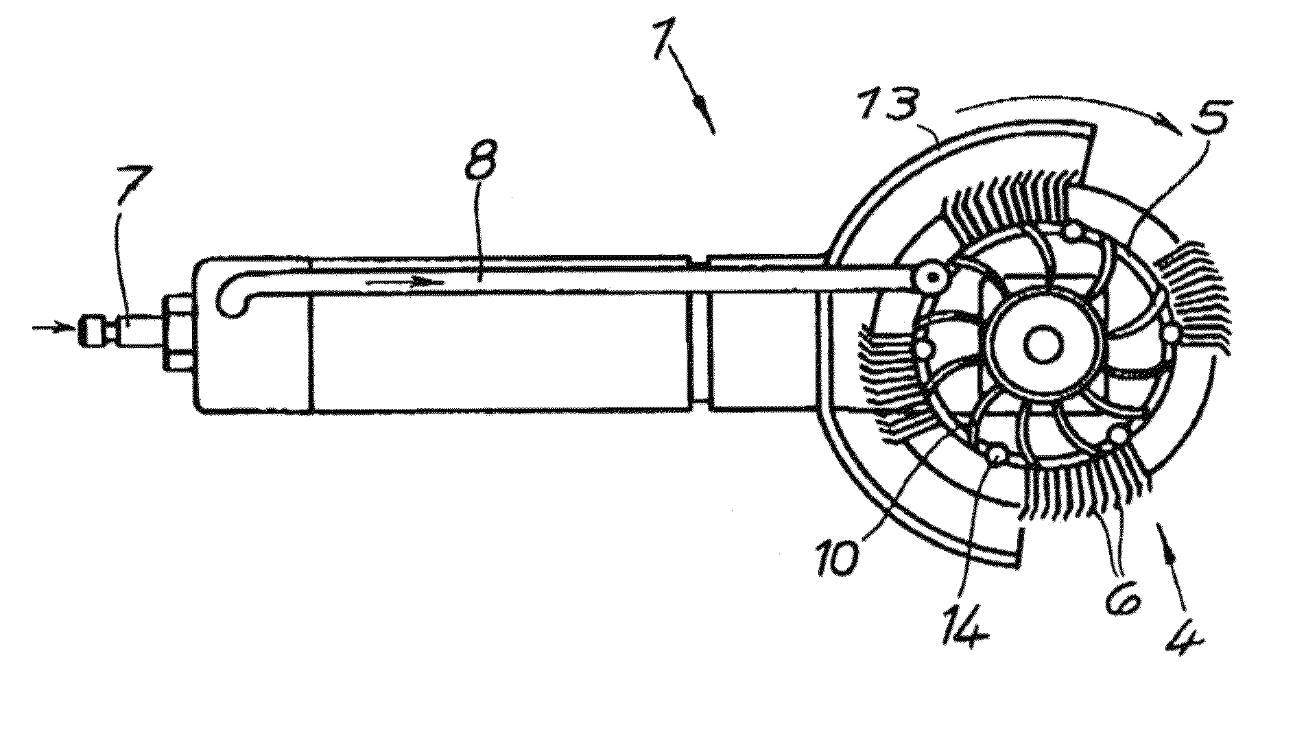
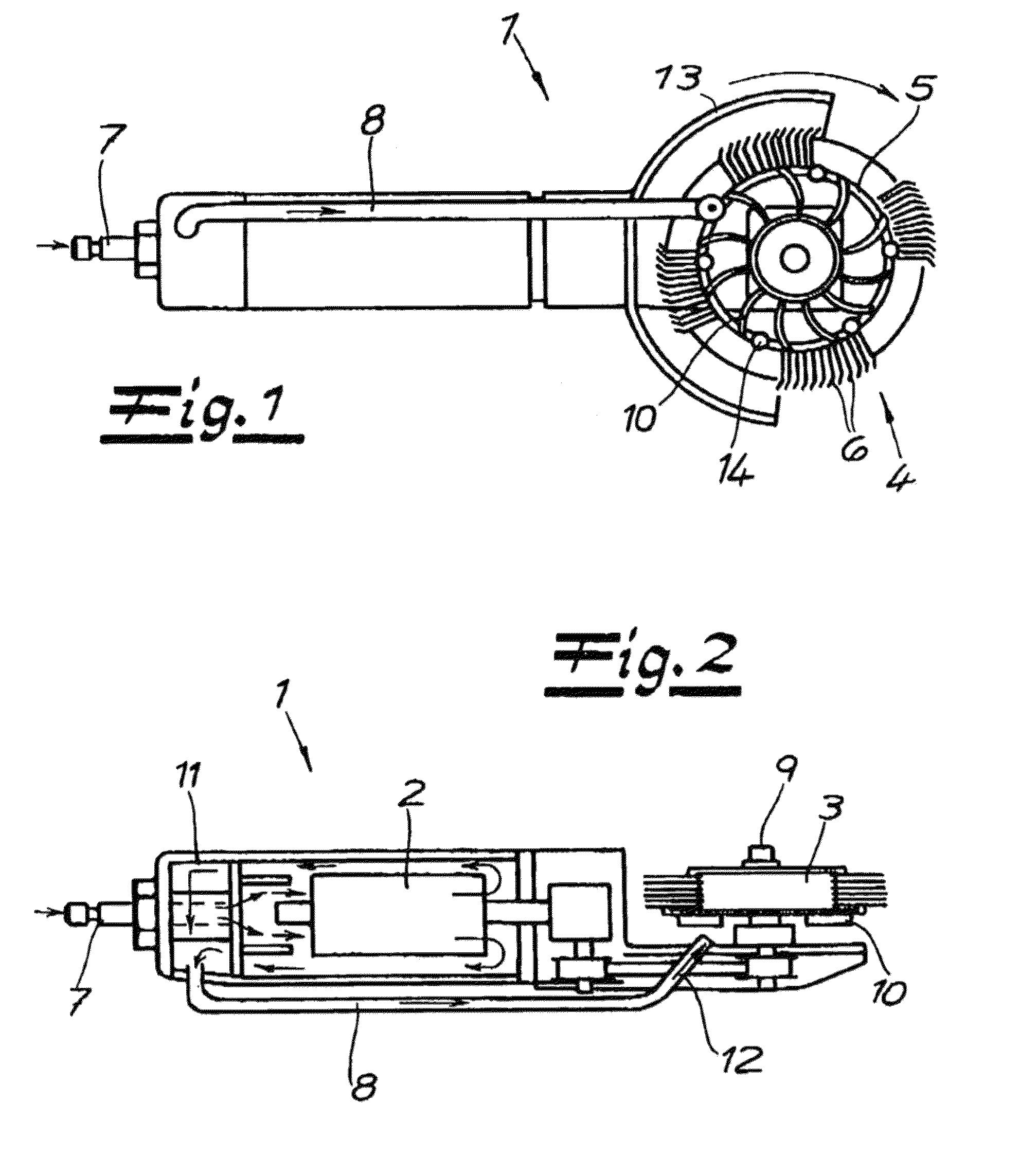
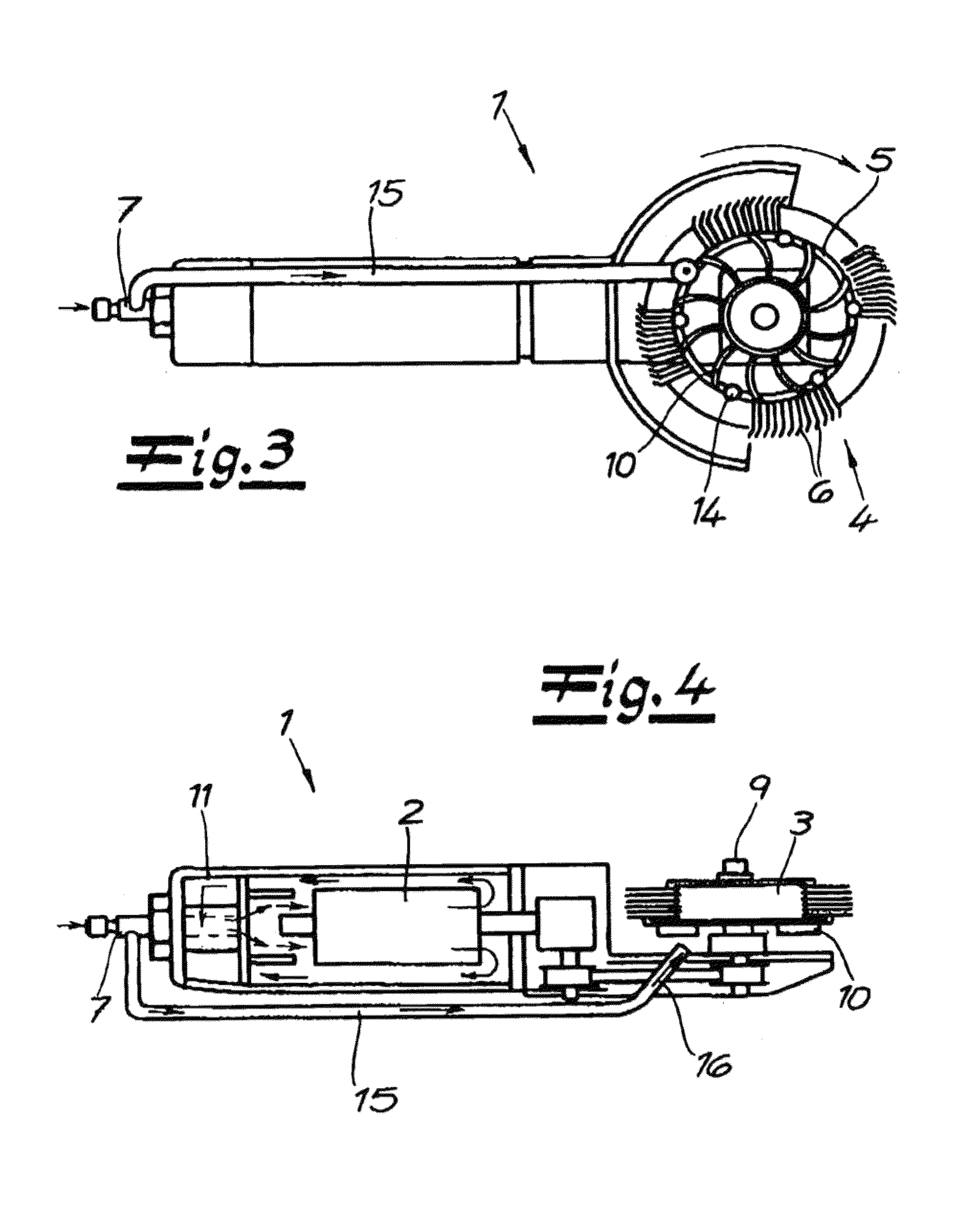
[0018]A rotary tool 1 for surface treatment is shown in FIGS. 1 and 2, which in its basic construction comprises a pneumatic drive 2 having a shaft 9 carrying a tool holder 3 which can be driven in rotation, according to the embodiment a brush holder 3, for an annular brush 4 with a brush strip 5 and bristles 6 protruding outwardly from the brush strip 5. The bristles 6 are, in particular and in a non-limiting manner, wire bristles. Furthermore a compressed air supply 7 is provided for the pneumatic drive 2.

[0019]According to a first alternative, as FIGS. 1 and 2 show, the exhaust air of the pneumatic drive 2 is supplied via an exhaust air line 8 to the brush holder 3 and / or the annular brush 4 with the bristles 6, as coolant for the cooling thereof. At the same time, the exhaust air provides torque assistance for the brush holder 3 driven in rotation. To this end, the brush holder 3 on the exhaust air side, i.e. facing an outlet end of the exhaust air line 8 on the exhaust air side...


PUM


Abstract

The subject of the present invention is a rotary tool (1) for surface treatment. This is equipped with a brush holder (3) which can be driven in rotation for an annular brush (4) with a brush strip (5) and bristles (6) protruding outwardly from the brush strip (5). According to the invention, coolant for the cooling thereof is supplied to the brush holder (3) and/or the annular brush (4).

Description

FIELD OF THE INVENTION[0001]The invention relates to a rotary tool for surface treatment, with a brush holder which can be driven in rotation and that carries an annular brush with a brush strip and bristles protruding outwardly from the brush strip. Such rotary tools are used as hand-held tools, in particular for paint removal, corrosion and underbody protection removal and for roughening metallic surfaces.BACKGROUND OF THE INVENTION[0002]A rotary tool of the above-described configuration is disclosed, for example, in DE 43 26 793 C1 (U.S. Pat. No. 5,524,315). The subject thereof is to ensure intensive surface treatment and moreover to achieve increased service life.[0003]Notwithstanding this, a polishing tool driven by compressed air is known from EP 0 691 181 B1, which nevertheless is not equipped with a brush holder for an annular brush with a brush strip. Instead, a polishing pad is driven in rotation. Additionally, a cooling air passage is used for injecting air through an air...

Claims


Application Information

Patent Timeline
IPC IPC(8): A46B13/06B24B23/02
CPCB24D13/18B24B23/026A46B13/005A46B13/06B24B55/02A46B2200/3093E02B3/125E02D17/202A01G9/02E02D2300/0051
Inventor MONTABAUR, WERNER
Owner MONTI WERKZEUGE
Why Eureka
Try Eureka