
Light-based touch surface with curved borders and sloping bezel

a touch input surface and light-based technology, applied in the field of light-based touch input surfaces, can solve the problems of power consumption, screen not fully transparent, system versatility not enough to offer an all-encompassing solution, etc., and achieve the effect of minimizing light leakage and ensuring accuracy

Active Publication Date: 2014-03-18
NEONODE
View PDF19 Cites 11 Cited by
  • Summary
  • Abstract
  • Description
  • Claims
  • Application Information

AI Technical Summary

Benefits of technology

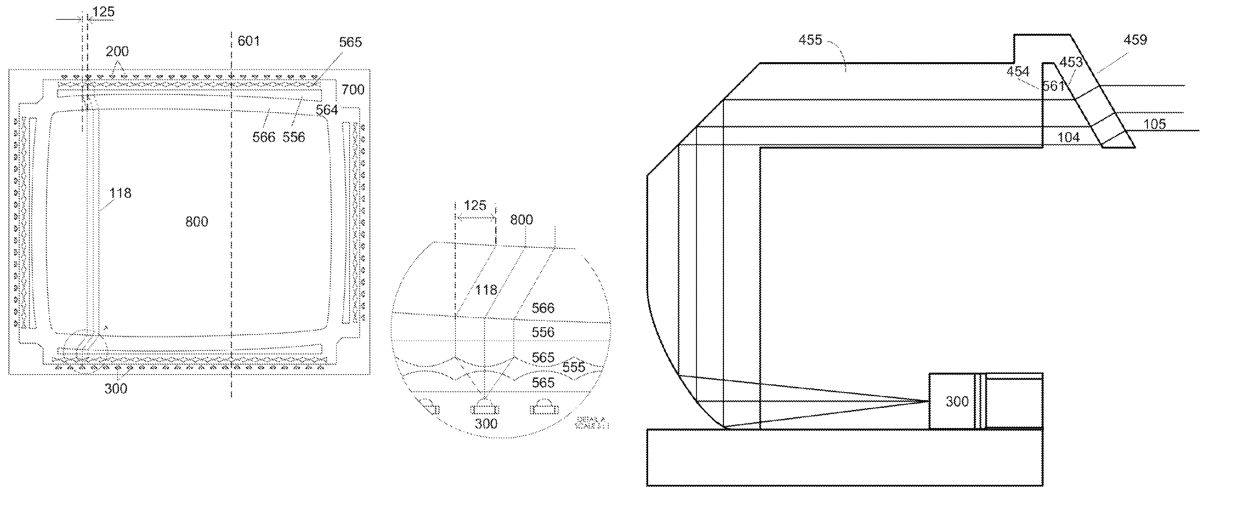
[0036]Aspects of the present invention provide special curved lenses for non-rectangular touch screens that are bordered by curved edges, so that a touch location may be easily and precisely determined. In one embodiment, the touch-sensitive portion of the non-rectangular touch screen is an inscribed rectangle, and the IR emitters and IR receivers are evenly spaced in straight rows.
[0037]Further aspects of the present invention provide sloped bezels for touch screen light guides, which minimize light leakage.

Problems solved by technology

Such systems are not versatile enough to offer an all-encompassing solution, as they are not easily scalable.
Advantages of resistive touch screens are their low cost, low power consumption and stylus support.
A disadvantage of resistive touch screens is that as a result of the overlay, the screens are not fully transparent.
Another disadvantage is that pressure is required for touch detection; i.e., a pointer that touches the screen without sufficient pressure goes undetected.
As a consequence, resistive touch screens do not detect finger touches well.
Another disadvantage is that resistive touch screens are generally unreadable in direct sunlight.
Another disadvantage is that resistive touch screens are sensitive to scratches.
Yet another disadvantage is that resistive touch screens are unable to discern that two or more pointers are touching the screen simultaneously, referred to as “multi-touch”.
A disadvantage of surface capacitive touch screens is that as a result of the overlay, the screens are not fully transparent.
Another disadvantage is a limited temperature range for operation.
Another disadvantage is a limited capture speed of pointer movements, due to the capacitive nature of the touch screens.
Another disadvantage is that surface capacitive touch screens are susceptible to radio frequency (RF) interference and electromagnetic (EM) interference.
Another disadvantage is that the accuracy of touch location determination depends on the capacitance.
Another disadvantage is that surface capacitive touch screens cannot be used with gloves.
Another disadvantage is that surface capacitive touch screens require a large screen border.
As a consequence, surface capacitive touch screens cannot be used with small screen devices.
Yet another disadvantage is that surface capacitive touch screens are unable to discern a mufti-touch.
A disadvantage of projected capacitive touch screens is that as a result of the overlay, the screens are not fully transparent.
Another disadvantage is their high cost.
Another disadvantage is a limited temperature range for operation.
Another disadvantage is a limited capture speed, due to the capacitive nature of the touch screens.
Another disadvantage is a limited screen size, typically less than 5″.
Another disadvantage is that surface capacitive touch screens are susceptible to RF interference and EM interference.
Yet another disadvantage is that the accuracy of touch location determination depends on the capacitance.
However, curved edges have a disadvantage in that light passing through a curved lens is distorted; in particular, collimated light beams emitted from a row of emitters do not emerge as collimate beams after passing through a conventional curved lens.
In turn, a precise touch coordinate cannot be determined based solely on an absence of expected light.
Sloped bezels have a disadvantage of light leakage due to refraction, whereby light beams refracted by a sloped bezel do not arrive at receivers.

Method used


Image

  • Light-based touch surface with curved borders and sloping bezel
  • Light-based touch surface with curved borders and sloping bezel
  • Light-based touch surface with curved borders and sloping bezel

Examples


first embodiment

[0360]Such three-sided lenses are used in several embodiments. In a first embodiment, the lens is used without an additional optical component with alternating facets for interleaving neighboring beams. In this embodiment, wide beams cover the screen but do not necessarily overlap to provide two or more detection signals for interpolation. A typical use case for this embodiment is finger input, but not stylus input. The tri-directional lens enables detection on four different axes, to eliminate ambiguity and ghosting in multi-touch cases. The tri-directional lens also provides additional touch location information; namely, four axes instead of two, and the additional information increases the precision of the touch location, even for a single touch.

second embodiment

[0361]In a second embodiment, the lens is used with an additional optical component with alternating facets for interleaving neighboring beams, or with an alternative arrangement providing overlapping detection signals. In this embodiment, overlapping wide beams provide two or more detection signals for interpolation. Typical use cases for this embodiment are finger and stylus input. The tri-directional lenses and the interleaving facets may be formed in two distinct components. The interleaving facets component is positioned closer to its emitter or receiver than the tri-directional component, since the tolerance for imprecise placement of the interleaving facets component is low, whereas the tolerance for imprecise placement of the tri-directional lens component is high. Alternatively, the tri-directional lenses and the interleaving facets may be formed in a single rigid component. For example, a diffractive grating interleaves signals from two sources and also splits the beams in...


PUM


Abstract

A light-based touch-sensitive surface, including a housing, a surface attached to the housing for receiving touch input, a plurality of light sources in the housing for emitting light that crosses the surface, a plurality of light receivers in the housing for detecting the light emitted by the light sources, a curved lens adjacent to the surface through which the light emitted by the light sources passes, including two substantially similarly curved exterior panels, one of which forms a curved rim for the surface, and a calculating unit in said housing, connected to the light receivers, for calculating a touch location based on an absence of light expected to be received by the receivers.

Description

CROSS REFERENCES TO RELATED APPLICATIONS[0001]This application claims priority benefit of U.S. Provisional Patent Application Ser. No. 61 / 591,913, entitled LIGHT-BASED TOUCH SURFACE WITH CURVED BORDERS AND SLOPING BEZEL, filed on Jan. 29, 2012 by inventors Stefan Holmgren, Lars Sparf, John Karlsson, Anders Jansson, Thomas Eriksson, Joseph Shain, Niklas Kvist and Robert Pettersson, the contents of which are hereby incorporated herein in their entirety.[0002]This application is a continuation-in-part of U.S. application Ser. No. 13 / 424,592, entitled LIGHT-BASED FINGER GESTURE USER INTERFACE, filed on Mar. 20, 2012 by inventors Thomas Eriksson, Per Leine, Jochen Laveno Mangelsdorff, Robert Pettersson and Anders Jansson, the contents of which are hereby incorporated herein in their entirety.[0003]This application is a continuation-in-part of U.S. application Ser. No. 13 / 424,543, entitled OPTICAL ELEMENTS WITH ALTERNATING REFLECTIVE LENS FACETS, filed on Mar. 20, 2012 by inventors Stefan...

Claims


Application Information

Patent Timeline
Patent Type & Authority Patents(United States)
IPC IPC(8): G02B27/00G02B6/32
CPCG06F1/169G06F3/0421G06F2203/04806G06F1/1643G06F3/04883G06F2203/04808G06F1/1616B60K37/06G02B6/0001G02B6/0008G06F3/0412G06F3/042G02B6/32G06F2203/04104
Inventor HOLMGREN, STEFANSPARF, LARSKARLSSON, JOHNJANSSON, ANDERSERIKSSON, THOMASSHAIN, JOSEPHKVIST, NIKLASPETTERSSON, ROBERT
Owner NEONODE
Learn More