
Systems and methods for temperature control and heat extraction from waste landfills

a landfill and temperature control technology, applied in indirect heat exchangers, exothermal chemical reaction heat production, lighting and heating apparatuses, etc., can solve the problems of less information available on landfill heat generation, affecting the efficiency of landfill heat generation,

Active Publication Date: 2014-03-18
YESILLER NAZLI +1
View PDF8 Cites 5 Cited by
  • Summary
  • Abstract
  • Description
  • Claims
  • Application Information

AI Technical Summary

Benefits of technology

The invention is about a system and method for controlling and manipulating temperature to extract heat from the waste generated by industry and other sources. The system includes a network of heat extraction wells that circulate fluid containing a first circulation fluid to transfer heat to a second circulation fluid. The waste material undergoes various stages of biochemical reactions during which heat is created or absorbed. The system can adjust its heat output to manage these reactions as they progress. Overall, the invention allows for efficient heat extraction from waste and provides a sustainable solution for energy recovery.

Problems solved by technology

However, methane is an inflammable gas that not only can damage plants in a nearby area but also lead to a danger of explosion.
Additionally, emission into the atmosphere of the landfill gas contributes to the “greenhouse effect” as a direct factor to abnormal climate phenomena.
However, less information is available on heat generation in landfills.
Accordingly, optimal decomposition and gas production conditions are not uniform within a landfill mass.
However, such systems do not take advantage of a detailed analysis of spatial heat distribution or a long-term thermal trend of landfills.
In addition, systems are not available for controlling and manipulating temperatures in landfills.
Furthermore, current systems do not provide a method for creating a symbiotic energy source between the landfill and nearby facilities to create optimal operating conditions.

Method used


Image

  • Systems and methods for temperature control and heat extraction from waste landfills
  • Systems and methods for temperature control and heat extraction from waste landfills
  • Systems and methods for temperature control and heat extraction from waste landfills

Examples


Embodiment Construction

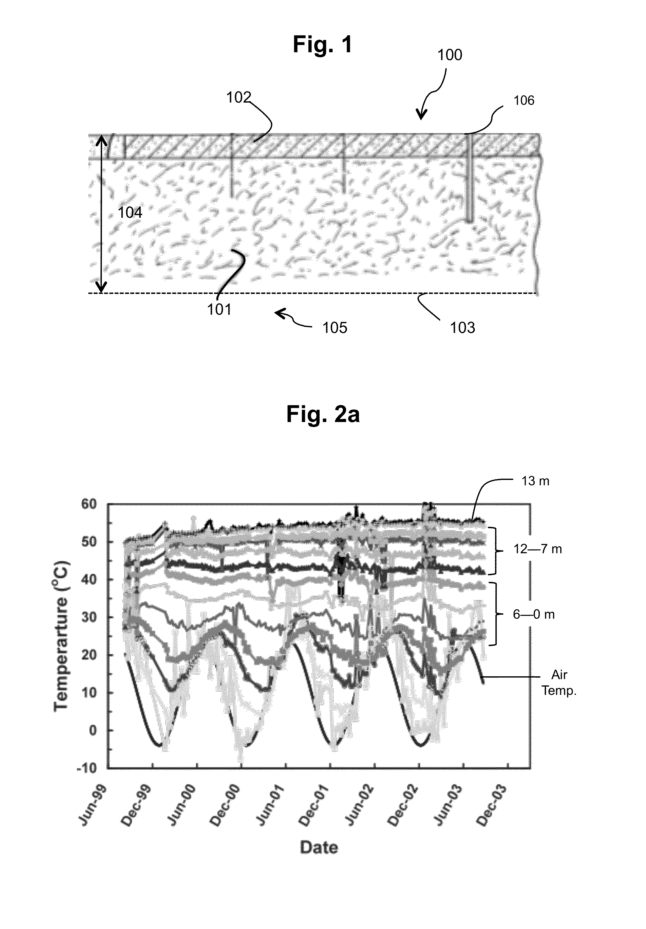
[0028]As described above, heat is generated as a result of biochemical processes and decomposition of organic components in wastes as well as chemical / biochemical transformation of various components in wastes. Field measurements of temperatures within landfills reveal spatial variations of temperature as a function of depth.

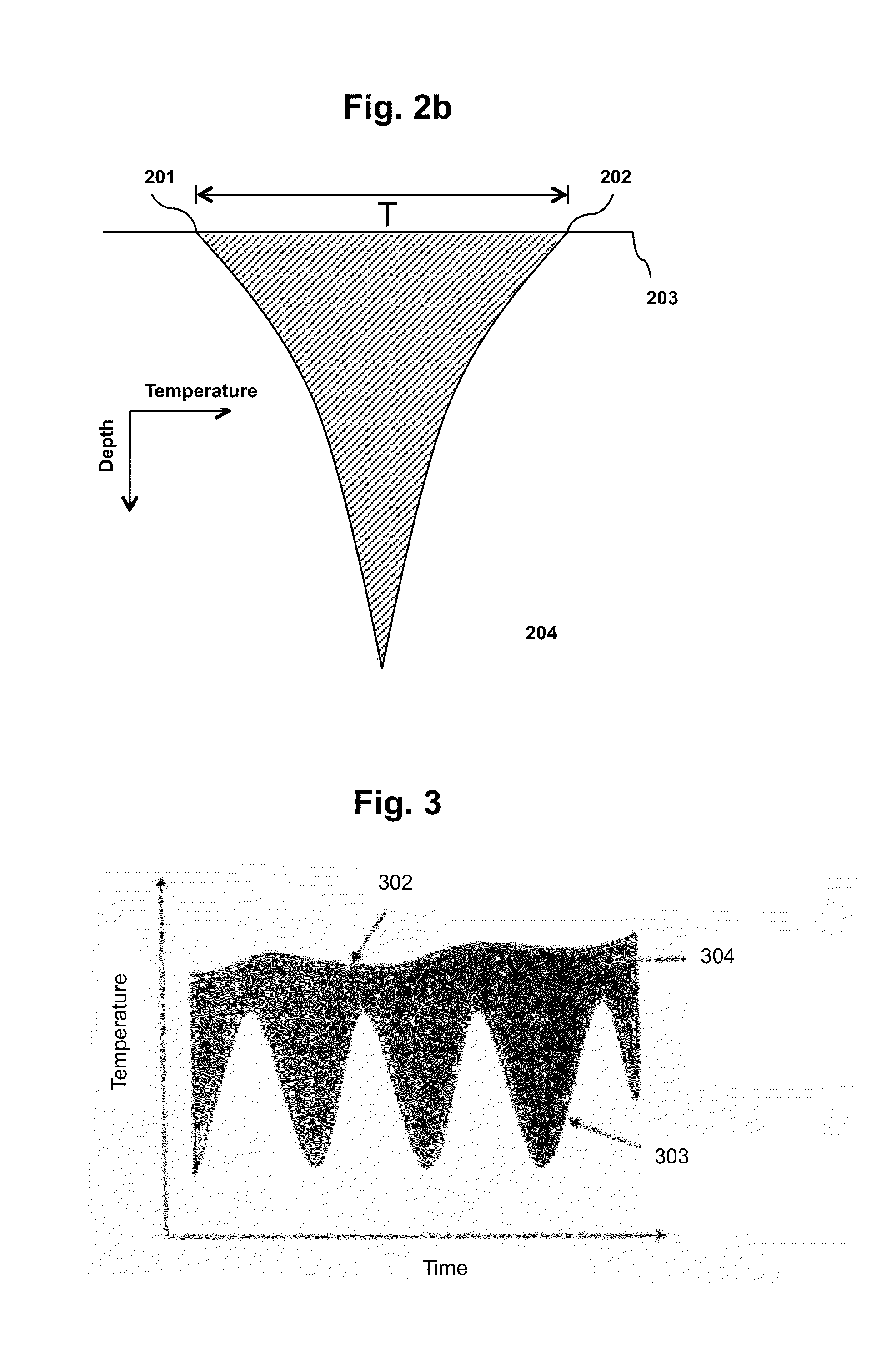
[0029]FIG. 2a illustrates an example of temporal variations in temperature with location at a given depth of waste landfill 100. Temperatures at relatively shallow depths of waste mass 101 (e.g., at the surface as well as near the edges / perimeter of the waste mass) undergo seasonal fluctuation similar to variability in earth temperature, which is shown in FIG. 2b. Turning to FIG. 2b, ground surface 203 provides range T of temperatures from low temperatures 201 (e.g., 0° C.) to elevated temperatures 202 (e.g., 40° C.). Elevated temperatures approach temperature 204, which is the mean annual earth temperature, as the measurement depth increases. Range T of tempera...


PUM


Abstract

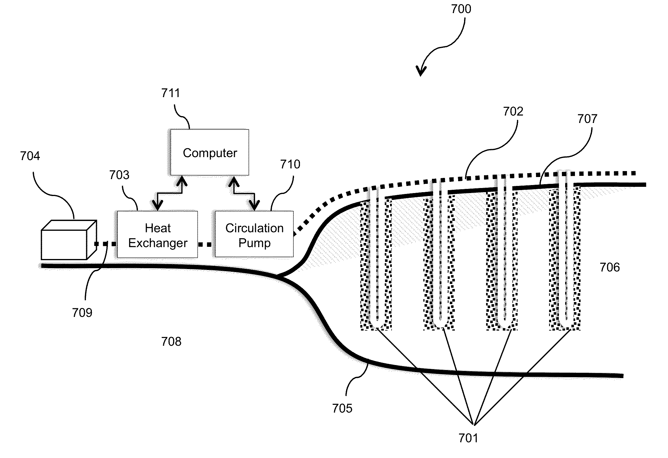
The field of the invention relates to systems and methods for exchanging heat from the degradation, decomposition, and chemical / biochemical transformation of municipal, industrial, and other types of waste. In one embodiment, a heat extraction system may include a closed-loop fluid circulation piping channeled throughout at least one heat extraction well oriented throughout a waste mass. The piping is fluidly coupled to a heat exchanger. A first circulation fluid is circulated through the closed-loop circulation piping into various depths of the waste mass to transfer thermal energy between said mass and said heat exchanger. In one embodiment, the transfer of thermal energy between the waste mass and the heat exchanger is used as alternative energy method and to control at least one of shear strength, compressibility, and hydraulic conductivity of the waste mass.

Description

FIELD OF THE INVENTION[0001]The field of the invention relates to systems and methods for temperature control and heat extraction, and more particularly to systems and methods for controlling and manipulating temperature and extracting heat from the degradation, decomposition, and chemical / biochemical transformation of municipal, industrial, and other types of waste.BACKGROUND OF THE INVENTION[0002]Continued increases in generation of industrial and municipal solid waste (MSW) has resulted in increased use of landfill sites worldwide. The U.S. Environmental Protection Agency estimates that the MSW generation in the U.S. is approximately 240 million tons (U.S. E.P.A. 2009). A significant portion of the waste is disposed of in landfills. As MSW landfills undergo normal operation, the primary byproducts of the landfill processes are heat, gas, and leachate (i.e., contaminated liquid generated due to passage of liquid through the waste mass). Significant amounts of other types of wastes...

Claims


Application Information

Patent Timeline
Patent Type & Authority Patents(United States)
IPC IPC(8): F24J1/00B09B1/00F24V30/00
CPCF25B27/02Y02A30/274
Inventor YESILLER, NAZLIHANSON, JAMES LEWIS
Owner YESILLER NAZLI
Learn More