
Aerodynamic drag reducer for a trailer

a technology of aerodynamic drag reducer and a trailer, which is applied in the direction of roofs, transportation and packaging, vehicle arrangements, etc., can solve the problem of not intended summary, and achieve the effect of preventing air turbulen

Inactive Publication Date: 2014-03-18
PFAFF RAIMUND
View PDF6 Cites 3 Cited by
  • Summary
  • Abstract
  • Description
  • Claims
  • Application Information

AI Technical Summary

Benefits of technology

[0008]A flat sheet member is secured to the lower ends of at least some of the cross-members and which extends therebetween to enclose the cross-members. When the trailer experiences a cross-wind, the air passing beneath the sides of the trailer is prevented from swirling upwardly into the spaces between the cross-members thereby preventing air turbulence therebetween which would otherwise create an aerodynamic drag upon the trailer thereby adversely affecting the fuel mileage of the tractor or truck pulling the trailer.

Problems solved by technology

Moreover, this Summary is not intended for use as an aid in determining the scope of the claimed subject matter.

Method used


Image

  • Aerodynamic drag reducer for a trailer
  • Aerodynamic drag reducer for a trailer
  • Aerodynamic drag reducer for a trailer

Examples


Embodiment Construction

[0019]Embodiments are described more fully below with reference to the accompanying figures, which form a part hereof and show, by way of illustration, specific exemplary embodiments. These embodiments are disclosed in sufficient detail to enable those skilled in the art to practice the invention. However, embodiments may be implemented in many different forms and should not be construed as being limited to the embodiments set forth herein. The following detailed description is, therefore, not to be taken in a limiting sense in that the scope of the present invention is defined only by the appended claims.

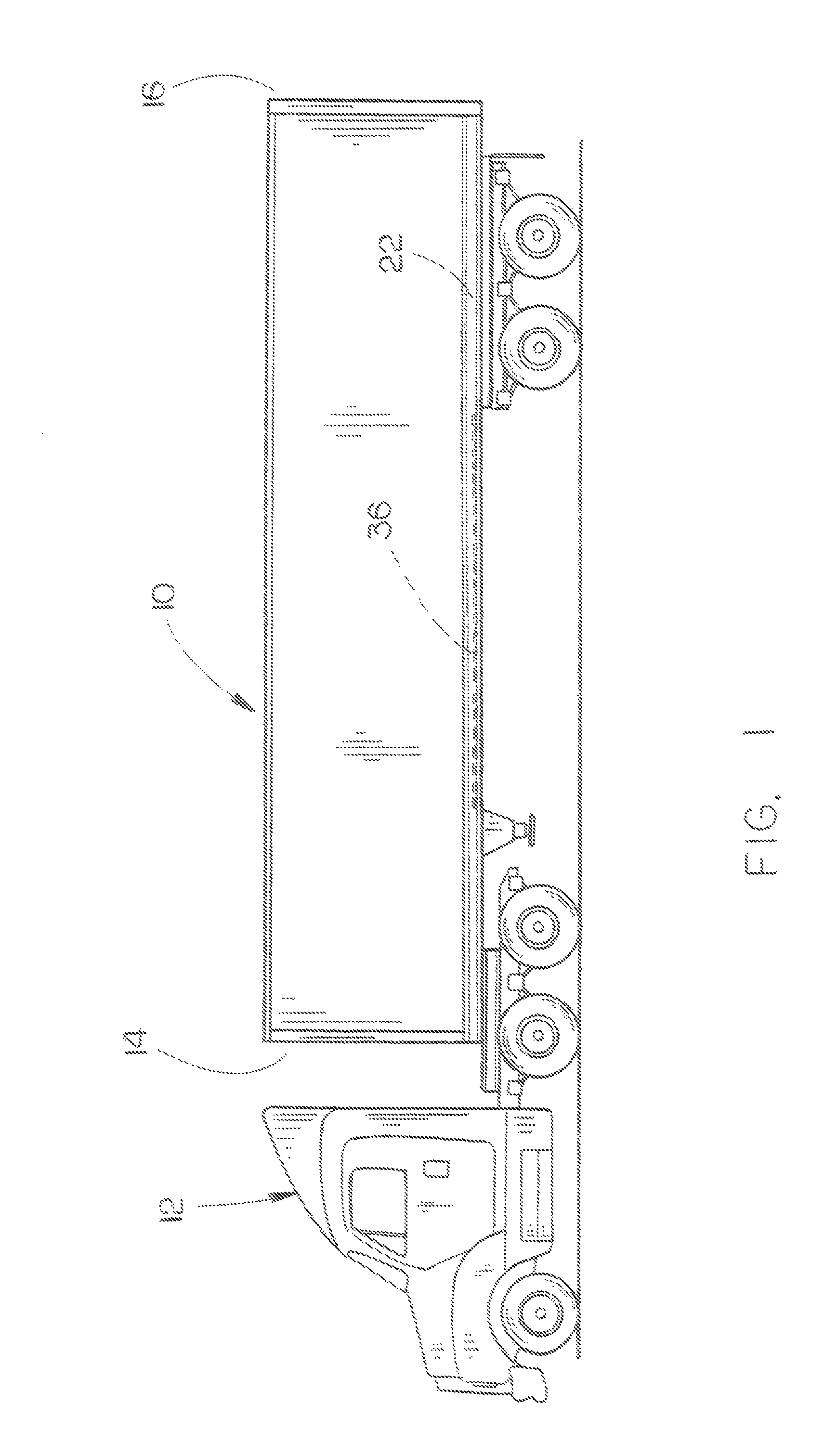
[0020]The numeral 10 refers to a conventional trailer which is designed to be pulled by a tractor or truck 12. Trailer 10 will be described as having a forward end 14, a rearward end 16, a left side 18 and a right side 20. Most trailers 10 have a left lower side rail 22 and a right lower side rail 24 which have the lower ends of side walls 20 and 28 secured thereto in conventional ...


PUM


Abstract

An aerodynamic reducer for a trailer comprising one or more sheet members which are secured to the lower ends of at least some of the cross-members positioned beneath the floor of the trailer. The sheet members enclose the space between at least some of the cross-members.

Description

BACKGROUND OF THE INVENTION[0001]1. Field of the Invention[0002]This invention relates to an aerodynamic drag reducer for a trailer and more particularly to an aerodynamic drag reducer for a trailer which is secured to some of the floor supporting cross-members thereof to enclose the cross-members to prevent the air flow of cross-winds from entering the space between the cross-members.[0003]2. Description of the Related Art[0004]A vast majority of trailers have right and left lower side rails which extend longitudinally along the lower sides of the trailer. A plurality of cross-members are secured to the lower side rails and extend therebetween to strengthen the trailer and to provide a support structure for the floor of the trailer.[0005]As the trailer is being pulled by a tractor or truck, the trailer is often subjected to cross-winds. As the air flow from a cross-wind passes beneath the side of the trailer, the air flow swirls and moves upwardly between the cross-members thereby ...

Claims


Application Information

Patent Timeline
Patent Type & Authority Patents(United States)
IPC IPC(8): B62D35/02B60R9/00
CPCB62D35/02B62D35/001Y02T10/82Y02T10/88
Inventor PFAFF, RAIMUND
Owner PFAFF RAIMUND
Learn More