Eureka AIR delivers breakthrough ideas for toughest innovation challenges, trusted by R&D personnel around the world.

Wireless energy transfer device

a wireless energy transfer and energy transfer technology, applied in the direction of transformer/inductance circuit, transformer/inductance details, inductance, etc., can solve the problem of difficult to efficiently receive electric power, and achieve the effect of suppressing the theft of wirelessly transferred energy

Active Publication Date: 2014-03-04
TOYOTA JIDOSHA KK
View PDF16 Cites 6 Cited by
  • Summary
  • Abstract
  • Description
  • Claims
  • Application Information

AI Technical Summary

Benefits of technology

[0009]The invention provides a wireless energy transfer device capable of suppressing the theft of wirelessly transferred energy.

Problems solved by technology

According to this configuration, as a result of changing the frequency of the oscillating magnetic field or the oscillating electric field generated by the power transmission unit, it becomes difficult to efficiently receive electric power even when attempting to steal transmitted electric power, thereby making it possible to suppress electric power theft.

Method used


Image

  • Wireless energy transfer device
  • Wireless energy transfer device
  • Wireless energy transfer device

Examples


first embodiment

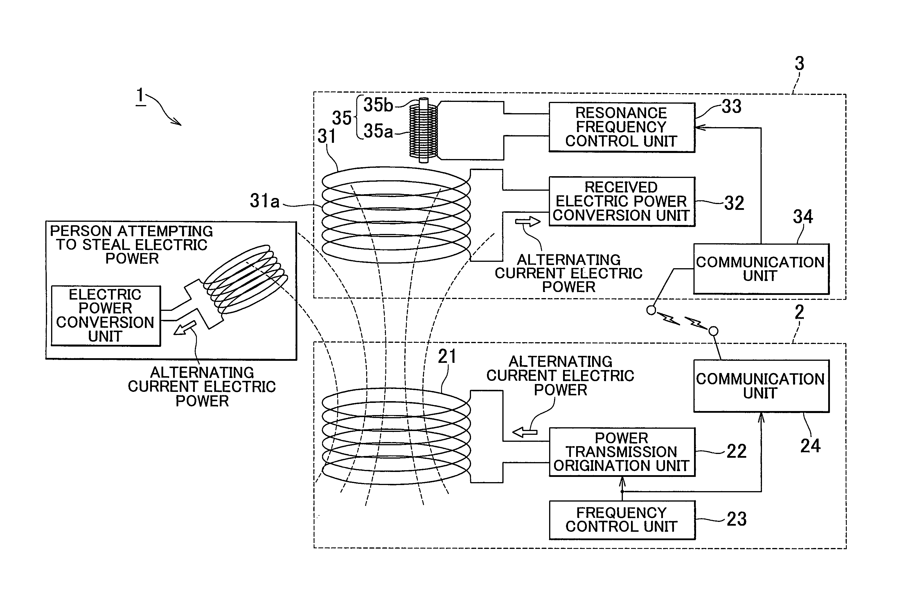
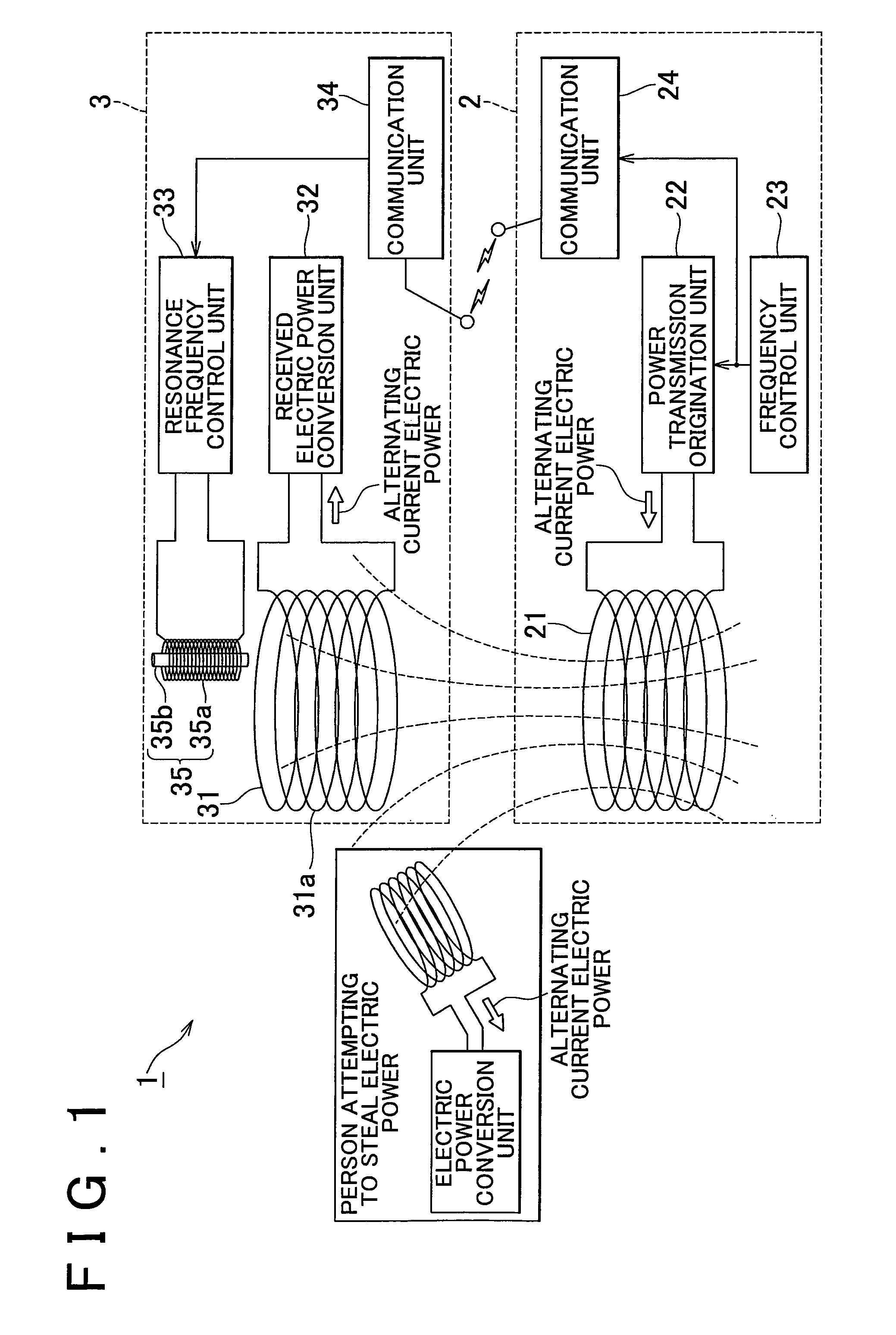
[0044]FIG. 1 is a block diagram of the configuration of a wireless energy transfer device according to the invention.

[0045]As shown in FIG. 1, a wireless energy transfer device 1 according to this embodiment is a device for wireless transfer of electric power energy from a power transmission unit 2 to a power reception unit 3.

[0046]The power transmission unit 2 generates an oscillating magnetic field, and is provided with a power transmission antenna 21, a power transmission origination unit 22, a frequency control unit 23, and a communication unit 24. The power transmission antenna 21 is an antenna for generating an oscillating magnetic field by inputting alternating current electric power, and a coil antenna, for examples, is used.

[0047]The power transmission origination unit 22 imparts alternating current electric power to the power transmission antenna 21, and for example, an oscillator having a variable oscillation frequency is used. The frequency control unit 23 controls the f...

second embodiment

[0076]FIG. 5 is a block diagram of the configuration of a wireless energy transfer device according to the invention.

[0077]As shown in FIG. 5, the wireless energy transfer device 1 is a device for wirelessly transferring electric power energy from a power transmission unit 2 to a power reception unit 3 in the same manner as the first embodiment.

[0078]In addition, differing from the power transmission unit 2 according to the first embodiment, the power transmission unit 2 according to this embodiment is provided with a detection unit 26, an electric power theft determination unit 27, and a notification unit 28. The detection unit 26 functions as a detection device for detecting an oscillating magnetic field formed in the vicinity of the power transmission unit 2, and is composed of a coil, for example. This detection unit 26 is installed, for example, at a location at a predetermined distance from the power transmission antenna 21. As a result, an oscillating magnetic field emitted b...


PUM

PropertyMeasurementUnit
magnetic fieldaaaaaaaaaa
electric fieldaaaaaaaaaa
electric poweraaaaaaaaaa

Abstract

A wireless energy transfer device (1) includes: a power transmission unit (2) that generates an oscillating magnetic field or oscillating electric field; a power reception unit (3), which is provided with a receiving antenna (31), and which converts the oscillating magnetic field or the oscillating electric field of the power transmission unit (2) to electric power by the receiving antenna (31); and an electric power theft suppression unit that suppresses the theft of energy with the oscillating magnetic field or the oscillating electric field of the power transmission unit (2).

Description

BACKGROUND OF THE INVENTION[0001]1. Field of the Invention[0002]The invention relates to an energy transfer device for carrying out wireless transfer of energy without the use of electrical wires and the like.[0003]2. Description of the Related Art[0004]The US 2006 / 0113955 A1 discloses a wireless charging and power system for electronic devices and a method for communicating power to a power receiver employing wireless energy transmission. The remote charging system includes a power transmission unit which transmits energy as a plurality of constructive transmitted frequencies and a power receiver system that receives the transmitted frequencies. The power receiver is preferably incorporated in a device and includes an energy receptor capable of receiving the wireless transmitted energy and transferring the energy from the transmitted frequencies to an energy storage device included in the device.[0005]The EP 1 022 840 A2 discloses a controller for a battery charger which inductivel...

Claims


Application Information

Patent Timeline
Patent Type & Authority Patents(United States)
IPC IPC(8): H01F27/42
CPCH02J17/00H02J50/60H02J50/80H02J50/12
Inventor FUKADA, YOSHIKI
Owner TOYOTA JIDOSHA KK
Why Eureka
Eureka Blog
Learn More