In-vehicle charging system

a charging system and vehicle technology, applied in the direction of vehicle position/course/altitude control, process and machine control, instruments, etc., can solve the problems of complex system relating to such communication, the general charger integrated with the display is not adapted to implement a communication process, and the place for mounting the charger in the vehicle as described above, so as to improve the functionality of the charging display and ensure the versatility of the system. , the effect of improving usability

Active Publication Date: 2014-02-25
SUZUKI MOTOR CORP
View PDF11 Cites 0 Cited by
  • Summary
  • Abstract
  • Description
  • Claims
  • Application Information

AI Technical Summary

Benefits of technology

[0018]An object of the present invention is to provide an in-vehicle charging system which improves a charging display function while ensuring system versatility and which improves usability by enhancing charging display content.
[0020]In the in-vehicle charging system according to the present invention, a charging display function can be improved while versatility of the system can be ensured, and usability can be also improved by enhancing charging display content.

Problems solved by technology

Also, a place for mounting the charger in the vehicle as described above is limited depending on various conditions.
However, even when information to be displayed is decided (i.e., a time required for completing charging of a battery), a general charger integrated with a display is not adapted to implement a communication process.
Thus, a system relating to such communication becomes complicated and its versatility is reduced.
When different battery capacities are provided in the same vehicle, individual components cannot be commonly used in the case in which the components are exclusively designed for each model.
Thus, mass production effect is unfavorably reduced.

Method used


Image

  • In-vehicle charging system
  • In-vehicle charging system
  • In-vehicle charging system

Examples


Embodiment Construction

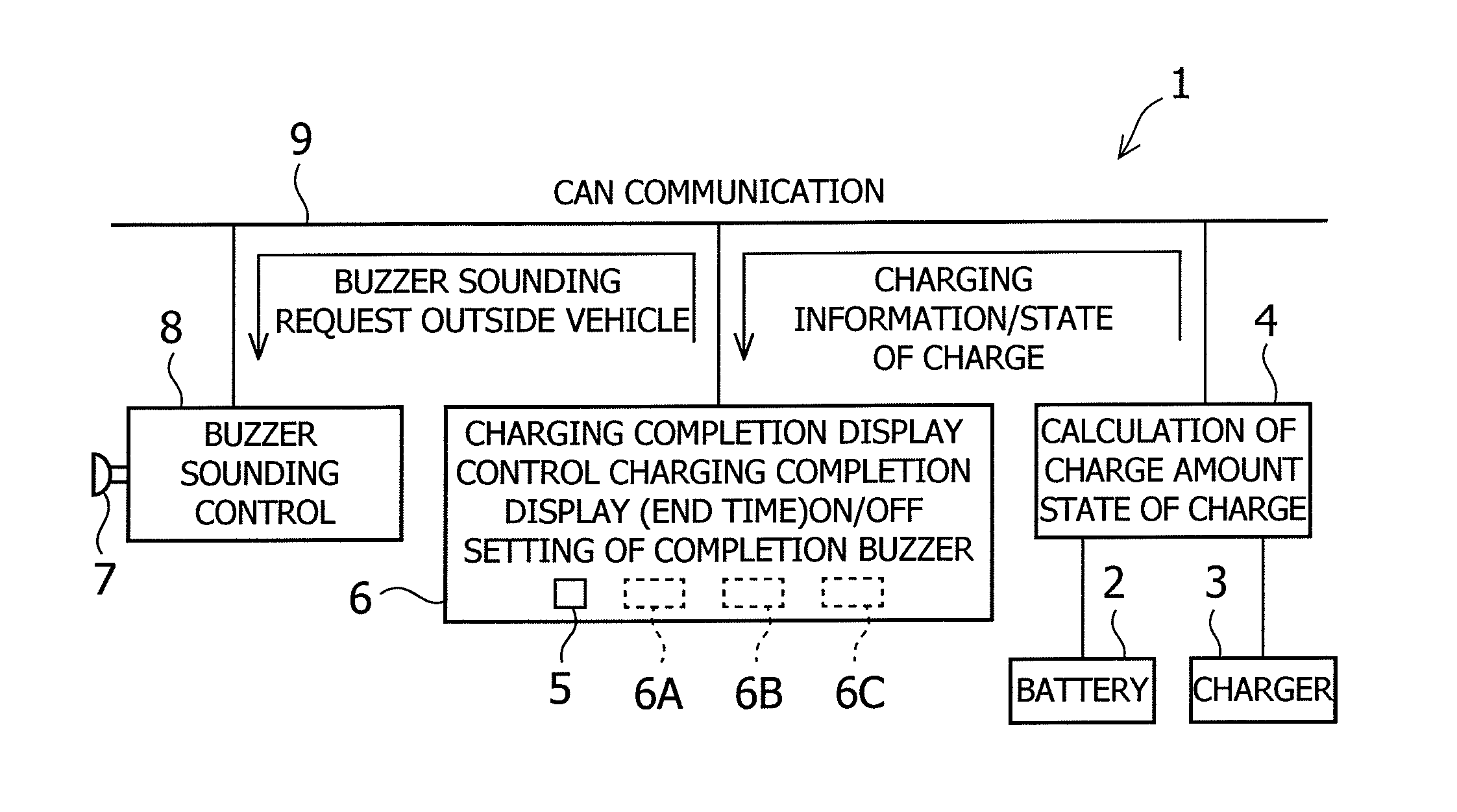
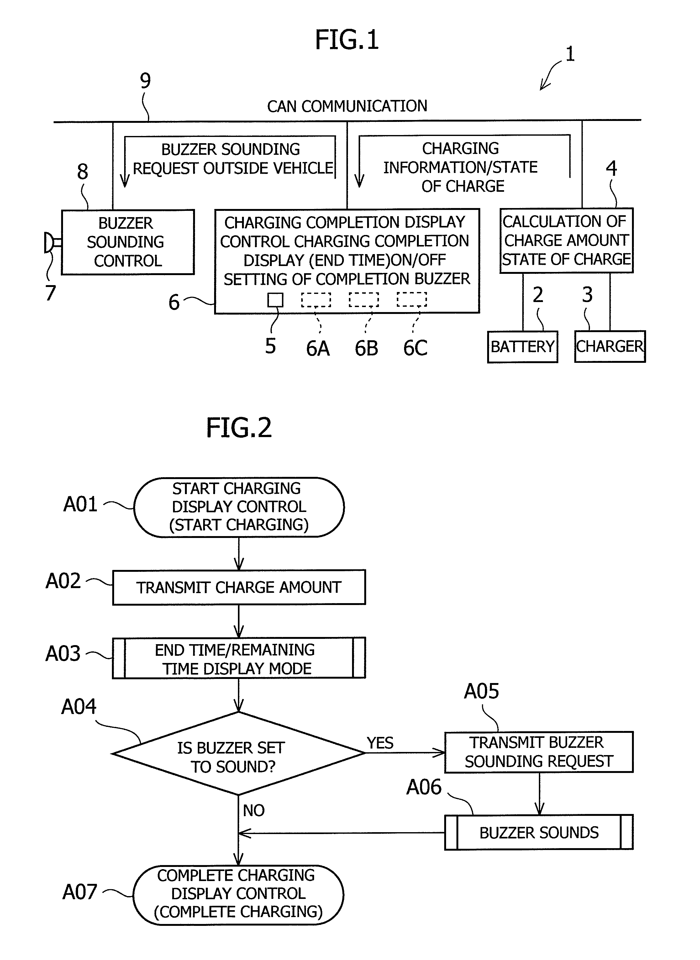
[0038]An object of the present invention, which improves a charging display function while ensuring system versatility and which improves usability by enhancing charging display content, is achieved by outputting a calculated charge amount and a state of charge of a battery to a communication line, calculating a time required for completing charging of a battery based on the charge amount and the state of charge of the battery received via the communication line, calculating an end time based on the required time to display the end time on a display while controlling colored lighting that indicates a remaining required time in accordance with the set time determined in advance.

[0039]FIGS. 1 to 5 show the embodiment of the present invention.

[0040]In FIG. 1, the reference numeral 1 denotes an in-vehicle charging system which is connected to an external power supply to charge a battery in a vehicle such as an electric vehicle (EV) and a hybrid electric vehicle (PHEV).

[0041]The in-vehic...


PUM


Abstract

In an in-vehicle charging system, a charging display function is improved while versatility of the system is ensured, and usability is improved by enhancing charging display content. An EV controller (4) calculates a charge amount and outputs the calculated charge amount and a state of charge of a battery (2) to a communication line (9). A meter device (6) calculates a time required for completing charging of a battery based on the charge amount and the state of charge of the battery received via the communication line (9), and then calculates an end time based on the required time to display the end time on a display (5) while controlling colored lighting that indicates a remaining required time in accordance with the set time determined in advance.

Description

CROSS-REFERENCE TO RELATED APPLICATIONS[0001]The present application claims priority to Japanese Patent Application No. 2011-112485, filed May 19, 2011, which is incorporated herein in its entirety.BACKGROUND OF THE INVENTION[0002]1. Field of the Invention[0003]The present invention relates to an in-vehicle charging system. More particularly, the present invention relates to an in-vehicle charging system which is connected to an external power supply to charge a battery in a vehicle such as an electric vehicle (EV) and a hybrid electric vehicle (PHEV) and which displays a charging condition by being connected to a controller via a communication line (LAN, CAN, or the like) mounted in the vehicle.[0004]2. Description of Related Art[0005]A vehicle such as an electric vehicle (EV) and a hybrid electric vehicle (PHEV) is generally provided with a display or charger that displays an end time for recognizing a charge completion time.[0006]The charger may include a display for displaying a...

Claims


Application Information

Patent Timeline
Patent Type & Authority Patents(United States)
IPC IPC(8): B60L9/00
CPCB60L11/1846B60L2260/58Y02T90/16B60L2210/30B60L2250/10B60L2250/16Y04S30/14Y02T90/14Y02T90/169Y02T90/128Y02T90/121Y02T10/7241B60L11/1816G01R31/3689Y02T10/7088Y02T90/127B60L2240/80Y02T10/7005Y02T90/163Y02T10/7072G01R31/371B60L53/14B60L53/65Y02T10/70Y02T10/72Y02T90/12Y02T90/167
Inventor HARAKI, TOSHIHISA
Owner SUZUKI MOTOR CORP
Why Eureka
Try Eureka