
Electronic circuit with a regulated power supply circuit

a technology of power supply circuit and electronic circuit, which is applied in the direction of electronic switching, pulse technique, instruments, etc., can solve the problems of unsatisfactory heating of the integrated circuit, and achieve the effect of reducing stability problems and reducing heating problems

Active Publication Date: 2014-02-25
NXP BV
View PDF15 Cites 0 Cited by
  • Summary
  • Abstract
  • Description
  • Claims
  • Application Information

AI Technical Summary

Benefits of technology

The invention provides a regulated power supply circuit that reduces stability and heating problems. It achieves this by integrating the regulated power supply circuit and the driver circuit of the output transistor. The driver circuit can initiate a rise or reduction in current through the output transistor at a predetermined rate that masks the unpredictable values of parameters of the output transistor. This slow response can be used to mask the variation of current through the output transistor. The driver circuit can also initiate a reduction in current when the indicated current through the output transistor is below a threshold level to reduce power supply noise. The driver circuit can be designed to ramp up or down the current through the output transistor at a predetermined rate upon detection of certain levels of current. This also makes it possible to reduce power supply noise.

Problems solved by technology

The second output transistor outside the integrated circuit serves to gradually take over supply of a part of the power supply current from first output transistor inside integrated circuit, when long term supply of that part from first output transistor would lead to undesirable heating of the integrated circuit.

Method used


Image

  • Electronic circuit with a regulated power supply circuit
  • Electronic circuit with a regulated power supply circuit
  • Electronic circuit with a regulated power supply circuit

Examples


Embodiment Construction

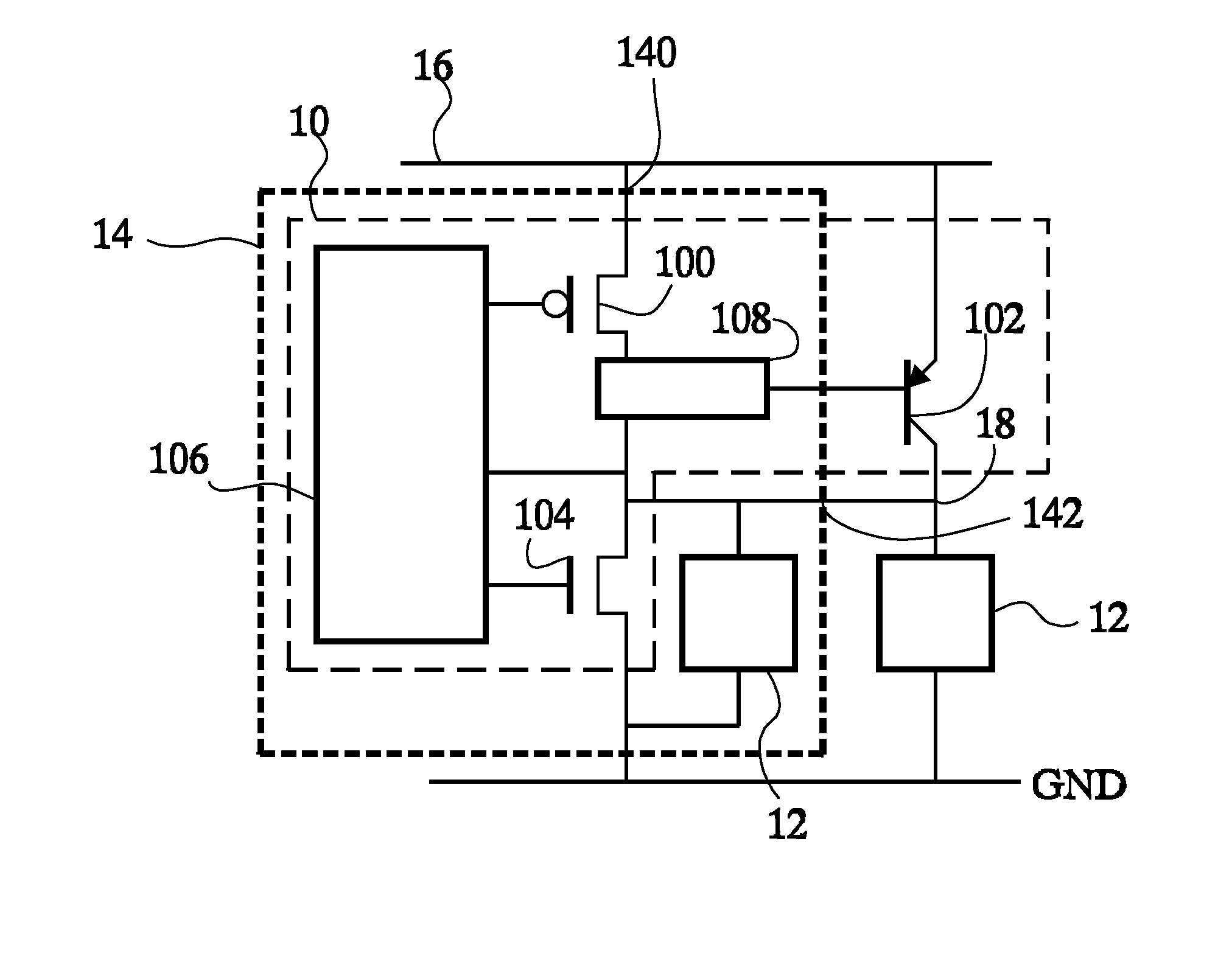
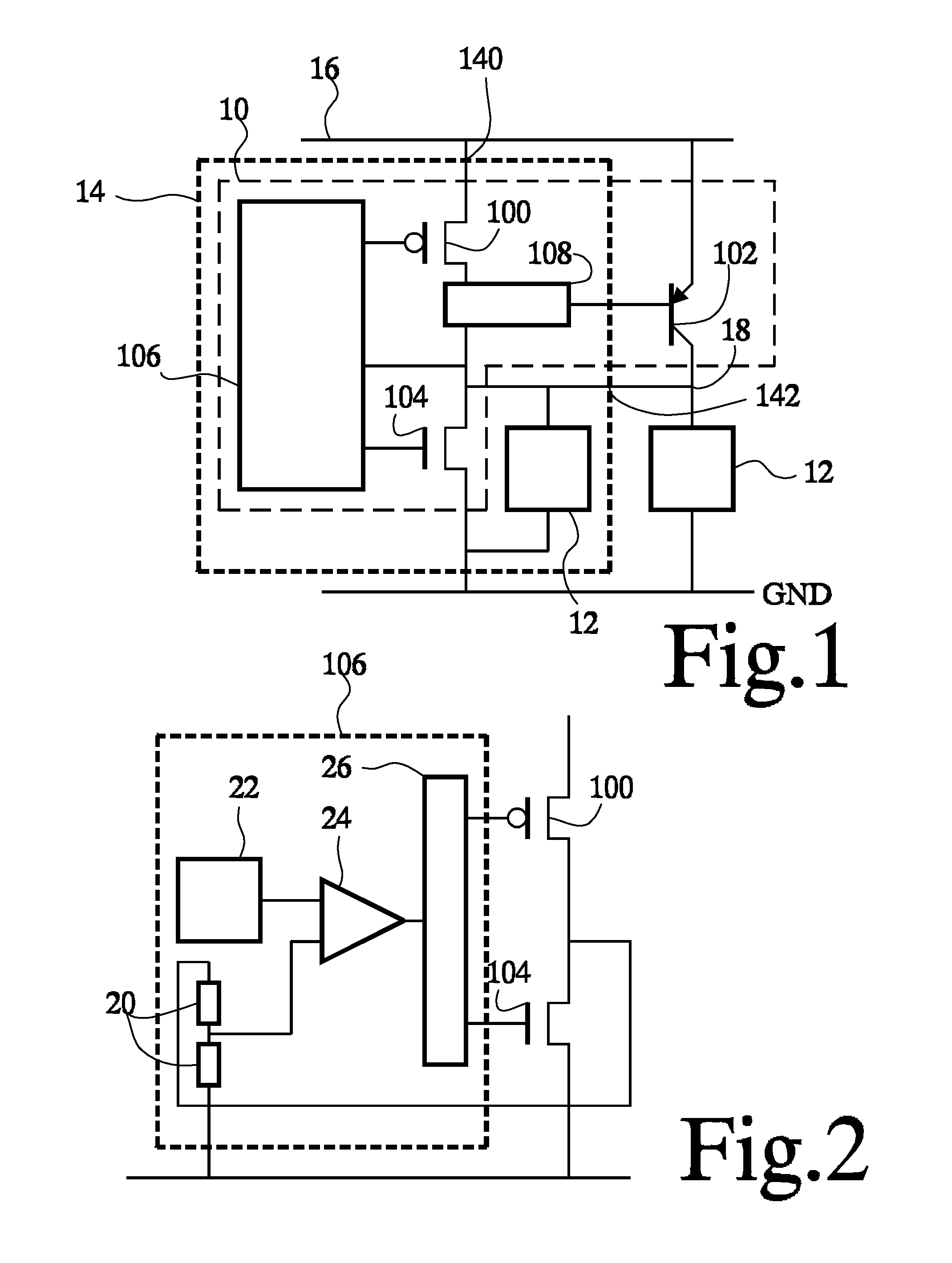
[0021]FIG. 1 shows an embodiment of an electronic circuit comprising a power supply control circuit 10 and further circuits 12. The further circuits 12 receive power supply input from power supply control circuit 10. The electronic circuit is partly integrated in an integrated circuit 14. The part of the circuit that is integrated in this integrated circuit 14 is indicated by a dashed box. The electronic circuit has a power supply input 16 and a regulated power supply output 18, coupled to a power supply input terminal 140 and a power supply output terminal 142 of integrated circuit 14.

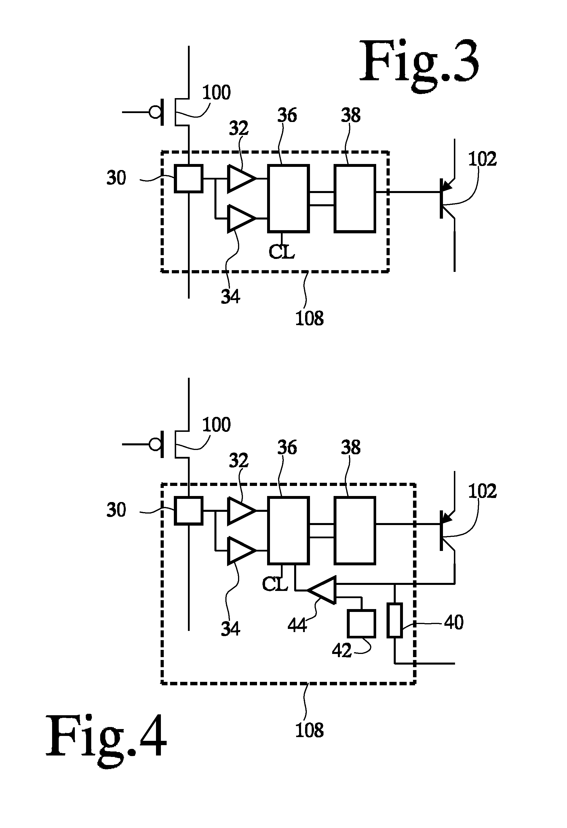
[0022]Power supply control circuit 10 comprises a first output transistor 100, a second output transistor 102, a pull-down transistor 104, a first driver circuit 106 and a second driver circuit 108. First output transistor 100, pull-down transistor 104, first driver circuit 106 and second driver circuit 108 are included in integrated circuit 14. Integrated circuit 14 may comprise a single semi-conduct...


PUM


Abstract

A power supply regulator circuit uses a feedback loop to control current through a first output transistor from a power supply input to a regulated power supply output. The first output transistor is included in an integrated circuit. In order to avoid heating of the integrated circuit in excess of an acceptable level due to permanent supply of a high current through the first transistor, current through a second output transistor in parallel with the first transistor, but outside the integrated circuit is raised when it is detected that the current through the first output transistor exceeds a threshold level. The second output transistor outside the integrated circuit serves to take over supply of a part of the power supply current from first output transistor inside integrated circuit, when long term supply of that part from first output transistor would lead to undesirable heating of the integrated circuit. During a limited time interval a first transistor current above the threshold level is acceptable. During this time interval the current through the second output transistor is raised slowly in order to avoid unpredictable stability problems and the generation of excessive power supply noise.

Description

FIELD OF THE INVENTION[0001]The invention relates to an electronic circuit with power supply circuit, an integrated circuit for use in such an electronic circuit and to a method of supplying power.BACKGROUND OF THE INVENTION[0002]U.S. Pat. No. 7,106,032 discloses a regulated power supply circuit with two parallel output transistors: a low power output transistor and a high power output transistor, the high power output transistor being switched on only when a high output current must be supplied. The output transistors are PMOS transistors with their channels coupled in parallel between the positive power supply source and the regulated output of the power supply circuit. The power supply transistors provide for a voltage drop between the positive power supply source and the regulated output. The output voltage at the regulated output is regulated by measuring this output voltage and using the measured output voltage to control the current through the output transistors.[0003]Thus, ...

Claims


Application Information

Patent Timeline
Patent Type & Authority Patents(United States)
IPC IPC(8): H03K17/16
CPCG05F1/565
Inventor WAGNER, MARTINBOEZEN, HENKDE HAAS, CLEMENS GERHARDUS JOHANNES
Owner NXP BV
Learn More