
Photobioreactor for algae growth

a photobioreactor and algae technology, applied in the field of microbe growth, can solve the problems of difficult temperature control, low yield, and inability to use genetically engineered microorganisms, and achieve the effects of less expensive construction, high yield, and easy maintenan

Inactive Publication Date: 2014-02-25
COVESTRO LLC
View PDF18 Cites 6 Cited by
  • Summary
  • Abstract
  • Description
  • Claims
  • Application Information

AI Technical Summary

Benefits of technology

The present invention is a flow-through photobioreactor that has several advantages. Firstly, the engineered microbes in the reactor produce higher yields without escaping into the environment. Secondly, the system prevents water from evaporating and avoids the need for weeding. Thirdly, the reactor filters out harmful UV light from sun, allows for temperature control, and can receive CO2 from power plants or breweries to increase yield. Compared to traditional pipe reactors, the photobioreactor is less expensive to build and operate with low energy costs.

Problems solved by technology

However, the open pond method has certain disadvantages including that genetically engineered microbes may not be used due to governmental regulations; water evaporates and thus must be replenished; the microbe culture is susceptible to contamination by other microbes that will result in lower yields; UV light from the sun kills microbes; it is difficult to control the temperature; and artificially feeding microbes with CO2 for higher yields is difficult.
Closed bioreactors too have disadvantages, such as being expensive to build; having higher energy costs to operate; bag reactors need less energy than pipe reactors that require the microbe solution to be pumped through the pipes; pipe reactors with high diameters need high turbulent flow to expose all algae to sunlight which results in high energy needs; pipe reactors with high diameters need high wall thicknesses which lowers the light transmission; and CO2 needs to be artificially fed.
The system and method also dampen thermal variations in the conduit.

Method used


Image

  • Photobioreactor for algae growth
  • Photobioreactor for algae growth
  • Photobioreactor for algae growth

Examples


Embodiment Construction

[0030]The present invention will now be described for purposes of illustration and not limitation. Except in the operating examples, or where otherwise indicated, all numbers expressing quantities, percentages, and so forth in the specification are to be understood as being modified in all instances by the term “about.”

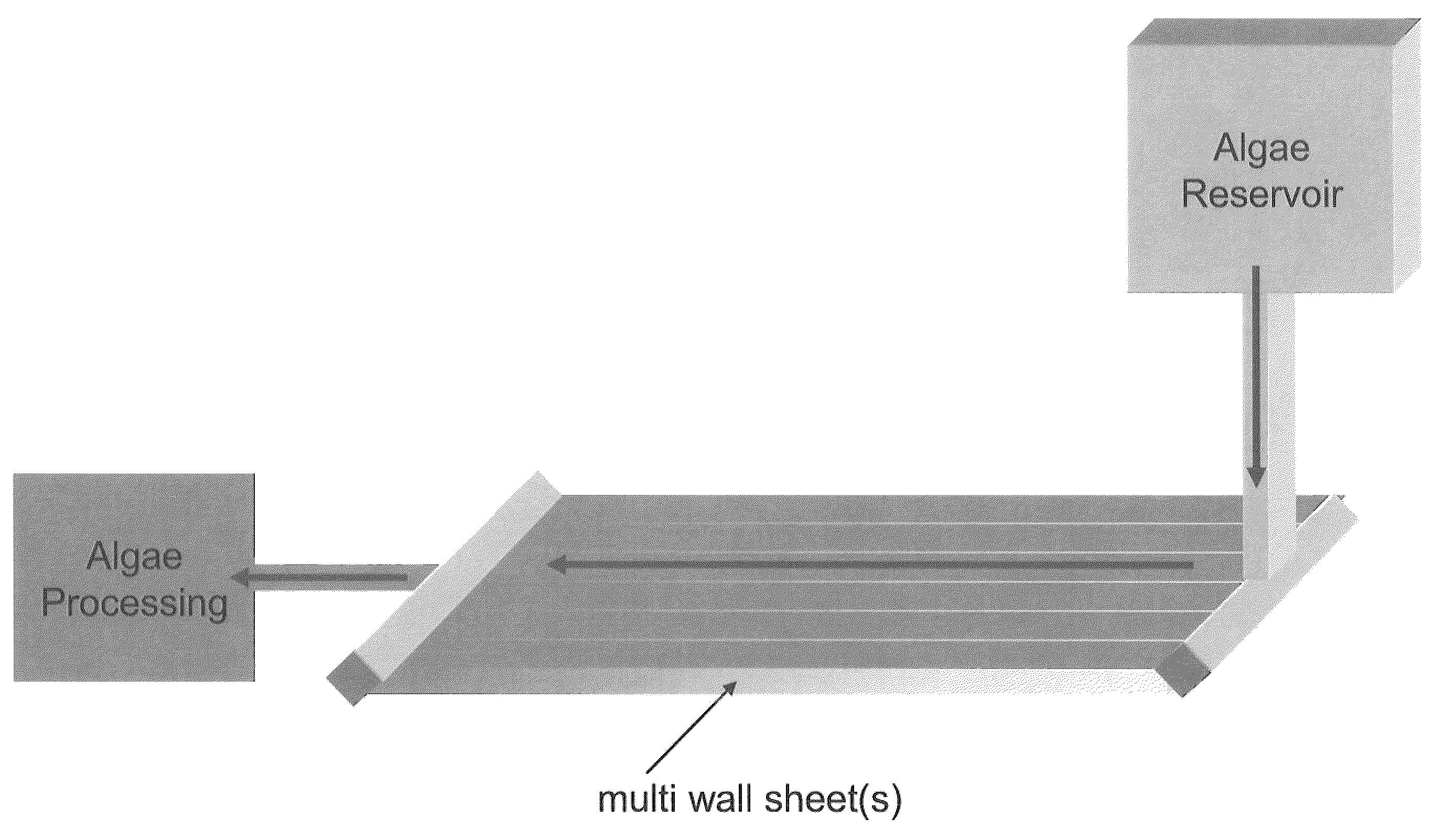
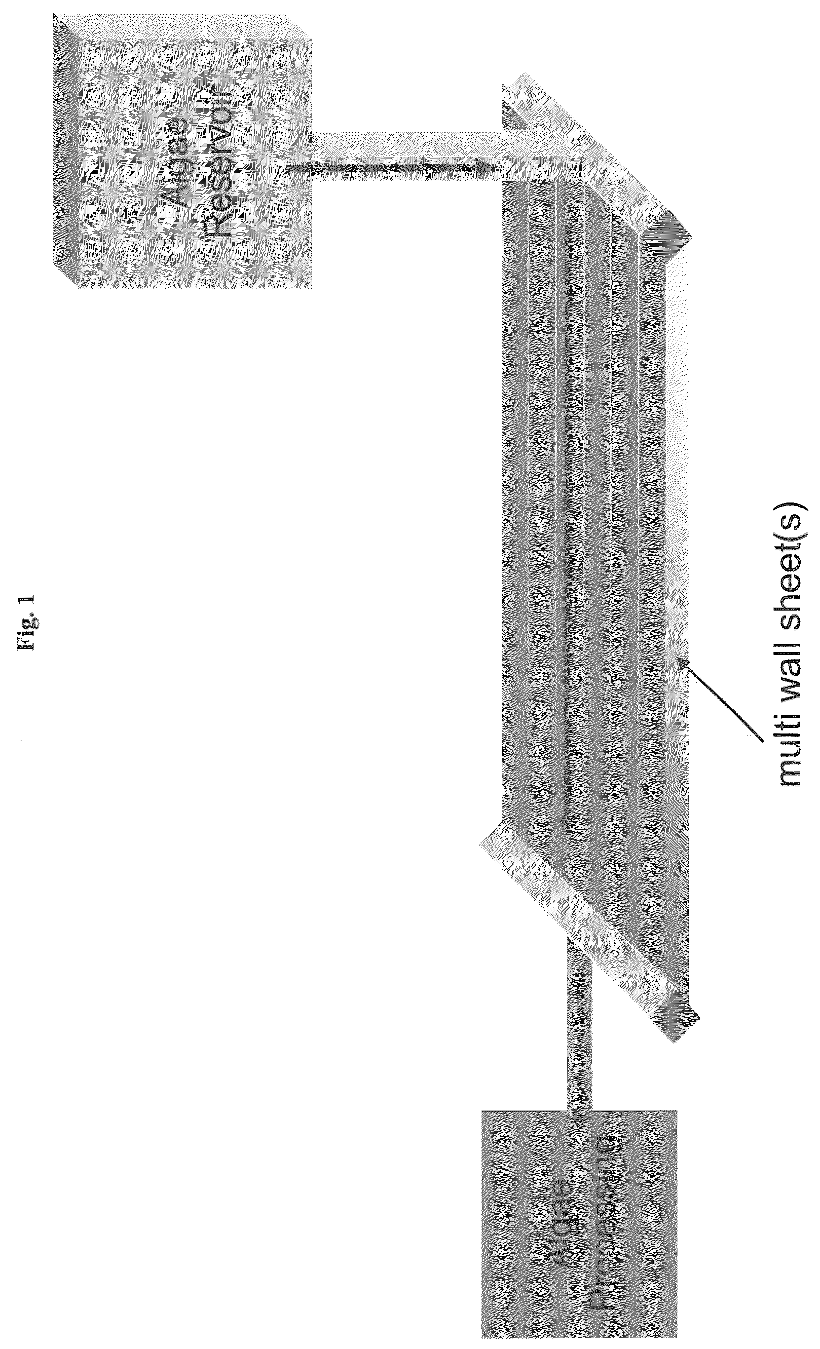
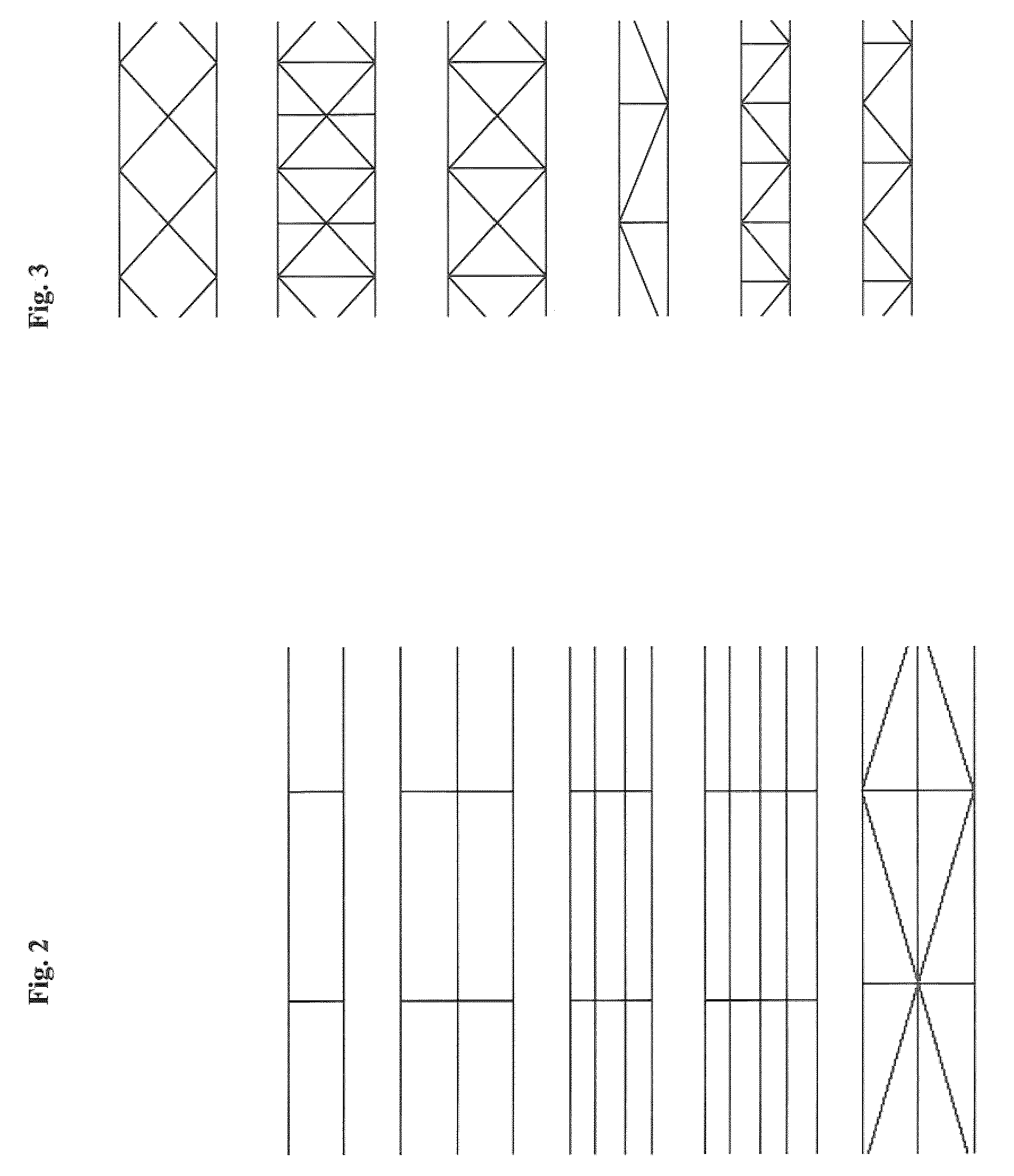
[0031]The present invention provides a flow-through photobioreactor containing at least one thermoplastic multi-wall sheet having an upper layer and a lower layer having arranged there between at least two sidewalls, at least one inner wall and two or more end caps.

[0032]The present invention further provides a process for the production of a biofuel involving flowing an algae solution into a flow-through photobioreactor containing at least one thermoplastic multi-wall sheet having an upper layer and a lower layer and having arranged there between at least two sidewalls, at least one inner wall and two or more end caps, exposing the algae solution to sunlight, harvest...


PUM

PropertyMeasurementUnit
thicknessaaaaaaaaaa
thicknessaaaaaaaaaa
thicknessaaaaaaaaaa

Abstract

The present invention provides a flow-through photobioreactor containing at least one thermoplastic multi-wall sheet having an upper layer and a lower layer having arranged there between at least two sidewalls, at least one inner wall and two or more end caps. Also provided is a process for the production of a biofuel with the inventive photobioreactor. The photobioreactor and process of the present invention have the following advantages: genetically engineered microbes that give higher yields cannot escape into the environment, water in the system does not evaporate, no weeding (presence of unwanted algae), UV light from the sun is filtered out by the reactor walls, temperature control is possible, CO2 from power plants, breweries, etc. can be artificially fed to increase yield. The inventive photobioreactor is also less expensive to build than pipe reactors and may have low energy costs to operate, because little or no energy is needed for agitation and pumping in a preferred gravity assisted embodiment.

Description

FIELD OF THE INVENTION[0001]The present invention relates in general to microbe growth and more specifically to a multi-wall thermoplastic, flow-through photobiorcactor for cultivation of algae for the production of biofuel.BACKGROUND OF THE INVENTION[0002]Due to the ever escalating price of petroleum and the increasing competition between foods and other biofuel sources, there is a greater interest in algaculture (farming algae) for making biofuels such as biodiesel, bioethanol, biogasoline, biomethanol, and biobutanol. One proposed benefit from the production of biofuels from algae lies in helping to stabilize the concentration of carbon dioxide in the atmosphere at its present level because during photosynthesis, algae and other photosynthetic organisms capture carbon dioxide and sunlight and convert those into oxygen and biomass.[0003]As those skilled in the art are aware, there are two basic processes used to grow microbes such as algae and / or bacteria, in large amounts e.g. fo...

Claims


Application Information

Patent Timeline
Patent Type & Authority Patents(United States)
IPC IPC(8): A01H13/00A01G9/00C12M3/00A01G7/00C12M1/00F21V33/00C12N1/12C12P7/649
CPCY02E50/17Y02E50/13C12M21/12C12P7/04C12P7/16C12M21/02C12M41/12C12P7/649C12P7/06C12M23/04Y02E50/10C12M23/34
Inventor GORNY, RUDIGERMASON, JAMES P.HILTON, GLENNSCHWARZ, PETER
Owner COVESTRO LLC
Learn More