
Laser device and operating method for it

a laser device and laser technology, applied in the field of laser devices and operating methods, can solve the problems of complex generation of laser pulses at a desired point in time while using passive q-switching systems, and achieve the effect of higher precision

Inactive Publication Date: 2014-02-25
ROBERT BOSCH GMBH
View PDF20 Cites 2 Cited by
  • Summary
  • Abstract
  • Description
  • Claims
  • Application Information

AI Technical Summary

Benefits of technology

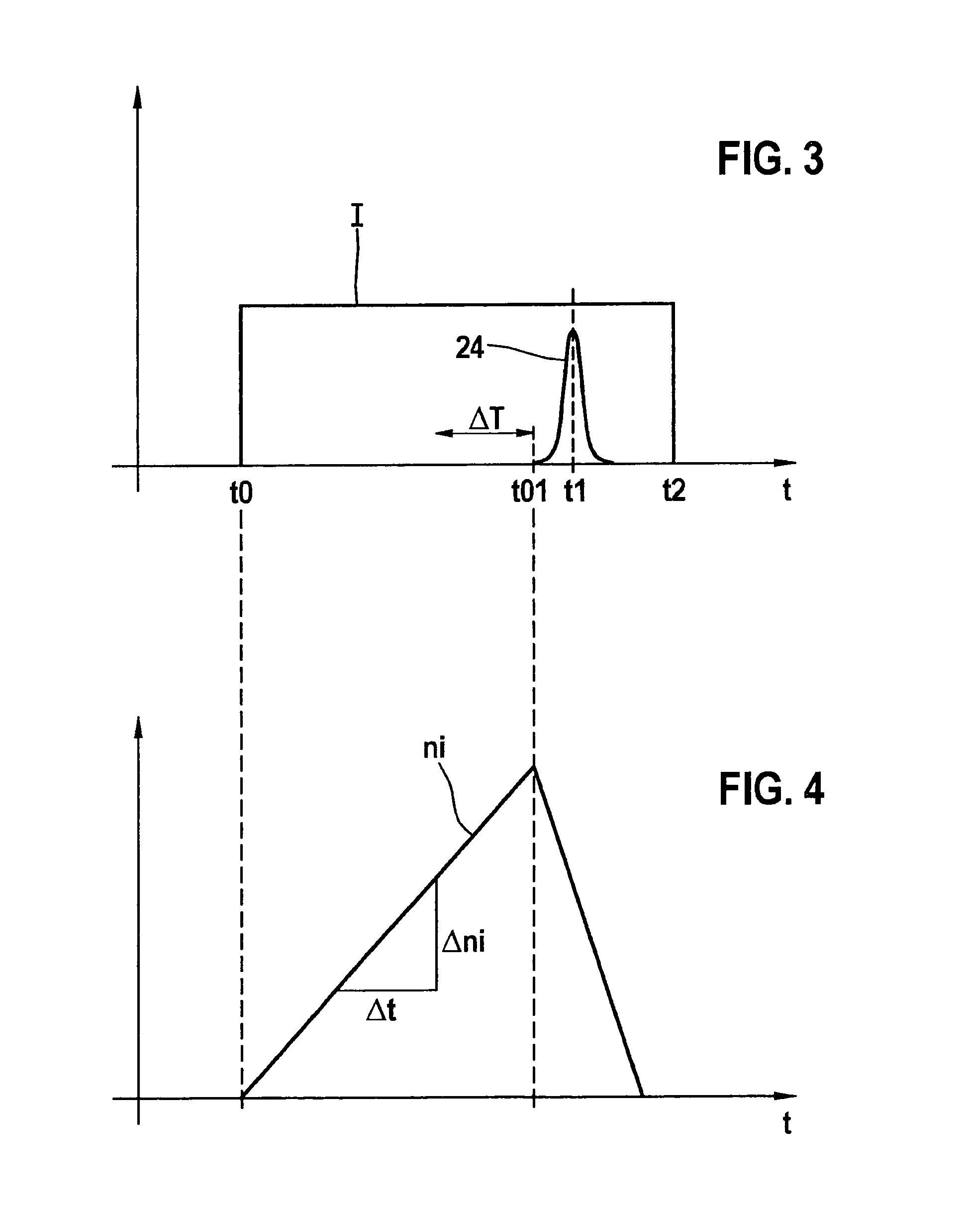
The present invention relates to a method for generating a passively Q-switched laser pulse using a laser device. The method involves acting on the laser device with pumping light to create an inversion density in the laser-active solid. The invention recognizes that not only the absolute value of the inversion density but also the curve over time of the inversion density affects the generation of a Q-switched laser pulse. By controlling the power density of the pumping light and selecting an optimal pumping duration, the method achieves a desired inversion density and operating behavior of the laser device. The method also allows for a nonconstant power density of the pumping light to protect the light source and increase precision with respect to the occurrence of the Q-switched laser pulse. The desired power density of the pumping light can be easily set by specifying a corresponding current through semiconductor laser diodes.

Problems solved by technology

By contrast to actively Q-switched laser devices, in which the time of generating a Q-switched laser pulse is able to be specified in a simple way by a corresponding activation of the active Q-switching, the generation of a laser pulse at a desired point in time while using passively Q-switched systems is far more complex.

Method used


Image

  • Laser device and operating method for it
  • Laser device and operating method for it
  • Laser device and operating method for it

Examples


Embodiment Construction

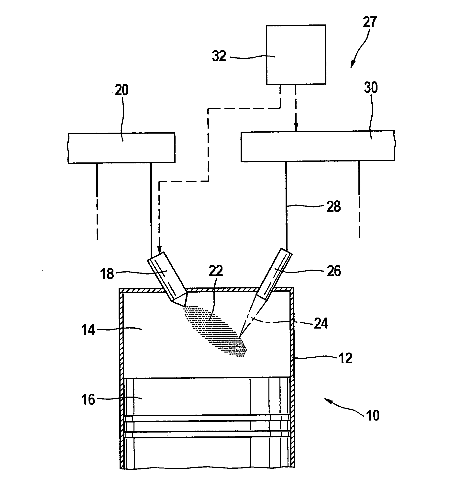
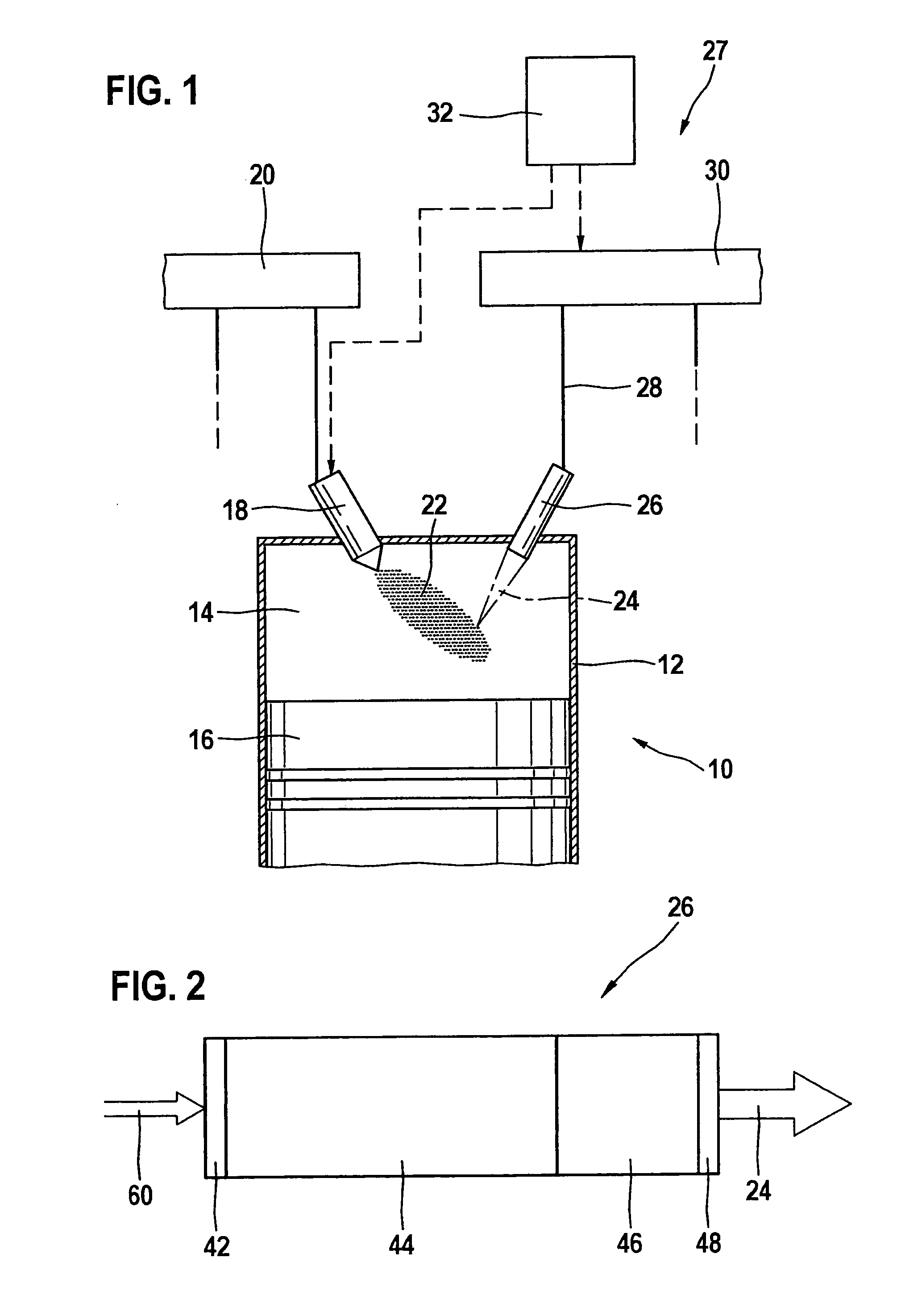
[0020]In FIG. 1, an internal combustion engine is denoted overall by reference numeral 10. It is used for driving a motor vehicle that is not shown. Internal combustion engine 10 includes a plurality of cylinders, only one of which is shown in FIG. 1 and denoted by reference numeral 12. A combustion chamber 14 of cylinder 12 is bounded by a piston 16. Fuel reaches combustion chamber 14 directly through an injector 18, which is connected to a fuel pressure reservoir 20 that is also designated as a rail, or rather, common rail.

[0021]Fuel 22 injected into combustion chamber 14 is ignited using a laser pulse 24, which is eradiated into combustion chamber 14 by an ignition device 27 which includes a laser device 26. For this purpose, laser device 26 is fed, via a light-guide device 28, with pumped light provided by a pumping light source 30. Pumping light source 30 is controlled by a control and regulating device 32, which also activates injector 18.

[0022]Pumping light source 30 preferab...


PUM


Abstract

In a method for operating a laser device, which has a laser-active solid having a passive Q-switch, the laser device is acted upon using pumping light in such a way that a specifiable curve over time of the inversion density comes about in the laser-active solid, as a result of which an especially precise control of the time behavior is achieved during the generation of passively Q-switched laser pulses.

Description

BACKGROUND OF THE INVENTION[0001]1. Field of the Invention[0002]The present invention relates to a method for operating a laser device which has a laser-active solid that has passive Q-switching. The present invention also relates to a laser device having a laser-active solid, passive Q-switching and a pumping source to act upon the laser device using pumping light.[0003]2. Description of Related Art[0004]By contrast to actively Q-switched laser devices, in which the time of generating a Q-switched laser pulse is able to be specified in a simple way by a corresponding activation of the active Q-switching, the generation of a laser pulse at a desired point in time while using passively Q-switched systems is far more complex.BRIEF SUMMARY OF THE INVENTION[0005]It is accordingly an object of the present invention to improve a laser device, and an operating method of the type named at the outset, to the extent that a higher precision is made possible in the generation of the passively Q...

Claims


Application Information

Patent Timeline
Patent Type & Authority Patents(United States)
IPC IPC(8): F02P23/04
CPCH01S3/1022H01S3/094053H01S3/094076F02P23/04H01S3/10046H01S3/09415H01S3/113H01S3/0627
Inventor RIDDERBUSCH, HEIKO
Owner ROBERT BOSCH GMBH
Learn More